
Label Manager3.0
User’s Guide
Edition 3.0.0
MapText, Inc.
www.maptext.com
Copyright © 2011 MapText, Inc.
All rights reserved.
Printed in the United States of America
Information contained herein is subject to change without notice.
November 2011
Label manager allows the user to configure labeling properties for MapText labeling products.
1. Setting up your data for labeling
Before using the product to label the features in your map, you need to set up the label properties for each layer you wish to label.
1.1. Label Manager Main Screen
Bring up the Label Manager dialog by clicking on the Label Manager icon in the
GeoLabel toolbar  or selecting the GeoLabel →Label Manager menu item. You should see a dialog showing a list of layers that are in the Legend for the currently open map window, similar to the one shown below.
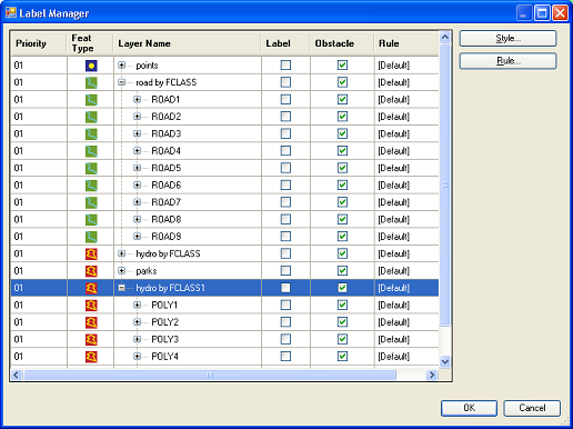
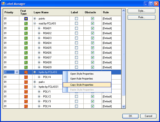
The Label Manager has the following columns (from left to right):
Priority. Feature layers can be assigned label-placement priorities, 1 being the highest and 12 being the lowest. Values for a layer can be changed by clicking on the value shown in the Priority column and selecting a different value from the pull-down menu.
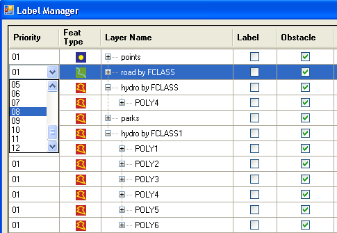
Feature type. Small icons indicate the type for each feature layer:  indicates area-feature layers,
  point-feature layers,
  line-feature layers and
  denotes layers with mixed feature types.
In case of mixed feature-type layers, the type to be labeled can be selected by a pull-down menu after clicking on the feature type icon as shown in the figure below. Either the line, point, or area icon must be selected; if the mixed feature-type icon is selected, then labeling CANNOT be turned on and labeling rules cannot be specified. In this case, the features of the layer can only act as obstacles.
Label. When this checkbox is checked for a feature layer, labeling will be performed for that layer. If unchecked, labels will not be placed for the layer.
Obstacle. When this checkbox is checked for a feature layer, its features will be treated as obstacles for the labels to be placed. If unchecked, the features will be invisible for label placement and thus labels will be allowed to cross those features.
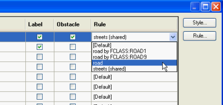
Rule. Indicates the name of the currently active text placement rule. Can be changed by the user. A previously defined rule can also be selected from a pull-down menu by clicking in the Rule column of that particular row (the list will also include previously created shared rules – see section on Shared Rules). To read more on rules, click here.
2. Style Properties dialog
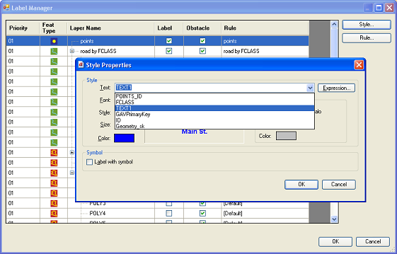
The Style Properties dialog allows users to set label style properties for each layer. Select the layer for which you need to set the Label Style and click on the Style button to bring up the Style Properties dialog.
2.1. Setting the Text for Labeling
The text to be used as label for the features of the layer can be set using either a single attribute or using an expression. For using the value from an attribute as the text, with the pull-down menu, select the attribute from which the label text should be extracted.
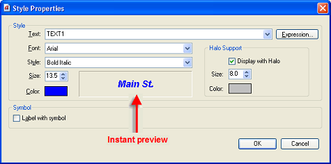
In the Style Properties dialog you also set the font properties for the Text such as font name, style, and color. You can also set the text halo properties. You can elect to display label text with a halo and, if so, set the halo size and color.
2.2. Defining Expressions for labeling
Label Manager allows the user to specify how labels are built from the text attributes. The Expression Builder can be launched by opening the Label Rule Manager and then clicking the Style and then the Expression buttons.
The Expression Builder contains an (A) expression box, (B) list of available commands, (C) available data fields, (D) operators, and (E) example and syntax. Instant expression validation is provided – an exclamation mark in the Expression box indicates when the expression is incorrect.
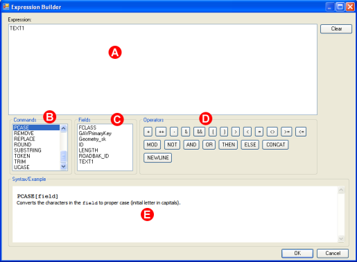
A detailed explanation of the Expression Builder, available commands and operators can be found in the Appendix.
Examples:
Example 1:
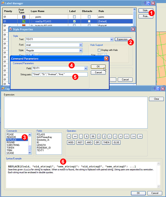
The following screens illustrate a rather typical expression when the user wants to display the string “St.” instead of “Street” and “Ave.” instead of “Avenue” on the map.
Bring up the Expression Builder by clicking the Style and then the Expression buttons (Steps 1 and 2). In the command menu of the Expression Builder, double click on the Replace command (Step 3), select the attribute on which the expression should be executed (Step 4), and build your expression (Step 5) according to the syntactic rules given in the Expression Builder (See 6 below).
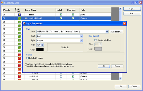
After clicking OK, you will see the expression in the Style Properties dialog.
Example 2:
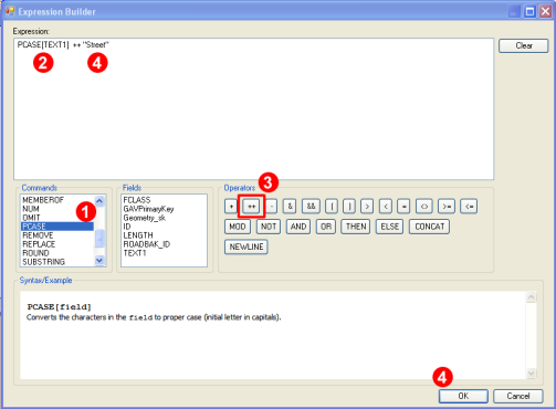
Data fields often contain only the name of the feature, and even that with lowercase. For example, the text field for a line feature (street) may only contain “wolfgang amadeus mozart”. On the map, however, it needs to appear as “Wolfgang Amadeus Mozart Street” with all initial letters in capitals. Label Manager’s expression builder helps carry out this conversion. The command PCASE converts the characters in the field (in this case TEXT1) to all initial capitals, and then we need to apply the ++ operator to concatenate “Street” at the end of TEXT1 with an intervening space.
Open the Expression Builder by clicking the Style and then the Expression buttons in the Label Rule Manager. In the command menu of the Expression Builder, double click on the PCASE command (Step 1); a dialog will appear. In that dialog select the attribute on which the expression should be executed (TEXT1), and build your expression (Step 2). This takes care of capitalizing initials.
After this click in the Expression box and type ‘++ “Street”’ or click the ++ operator in the Operator command group (Step 3) and type ‘”Street”’ after it. When finished, click OK (Step 4).
2.3. Labeling with symbols
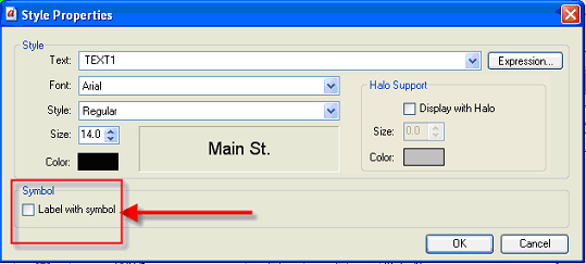
Label Manager allows the user to place the label inside symbols. A typical application is route shield placement:

The dialog can be opened by clicking the Label with Symbol (1) checkbox in the Style Properties dialog:
After this the Style Properties dialog will expand:
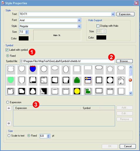
Symbol labeling can be performed with a fixed label (See 1 above) or with different symbols within a given layer based on the evaluation of an expression (3). For fixed symbols, select the symbol from the repository and click OK.
[ Note: The product comes with a default symbol repository
( install_folder\Symbols\shields.lsf ), but the user can select any compatible symbol file with .lsf extension. For more information on the .lsf file format, please contact MapText at support@maptext.com. ]
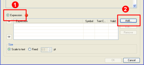
For the symbol to be defined by an expression, first click the Expression radio button (See 1 below) and then the “Add…” button (2):
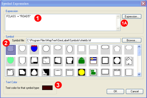
After clicking the Add button, the following window will pop up. If you are familiar with expressions, type it directly into the Expression field (see 1 in the image below). Alternatively, you can click on the Expression button (1A) and use the Expression builder to construct your expression.
The following scenario is illustrated in the example below: a line feature layer called “road” contains several types of roads (streets, county roads, highways). The type identifier is contained in the data field FCLASS. We want to label the highways within that feature layer with a highway shield of our choice (2). The highways are identified by ROAD5 in the FCLASS data field. The appropriate expression is FCLASS = “ROAD5”. Then select the symbol you want to use (Step 2) and the text color (Step 3), and click OK.
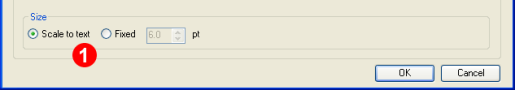
Users can specify the size of the symbol on the bottom of the Style Properties dialog (1). The options are: fixed size or scale to text. When fixed size is selected and specified in points, the symbol will fit into a square with sides equal to the selected value. If the text fits into the symbol, it is placed with the specified font size; else the text size is shrunk to fit within the symbol.
When “scale to text” is selected, the size of the symbol will vary and scale with the text size.
When the window is closed and labeling is performed (to be explained later), all the features of ROAD5 type will be labeled with the specified symbol:

2.4. Mass configuration
Some datasets may contain tens or hundreds of layers. It is easier in such a case to copy and paste labeling style configuration than to define each one individually. For this a user has a copy context menu option available when right-clicking on a layer.
Once you copy a desired layer’s style, you can paste it over any selection of layers. Just Shift (or Ctrl) select multiple layers, right click and choose paste.
3. Setting up rules for labeling
Label Manager provides users with an intuitive, easy-to-understand interface for setting up labeling rules for point, line, and area features. Users need to check the Label checkbox in the Label Rule Manager for requesting labeling for a particular layer. There are default rules defined for each feature type.
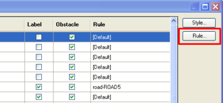
To set up rules select a feature layer in the Label Rule Manager and click the Rule button:
3.1. Labeling rules for POINT features
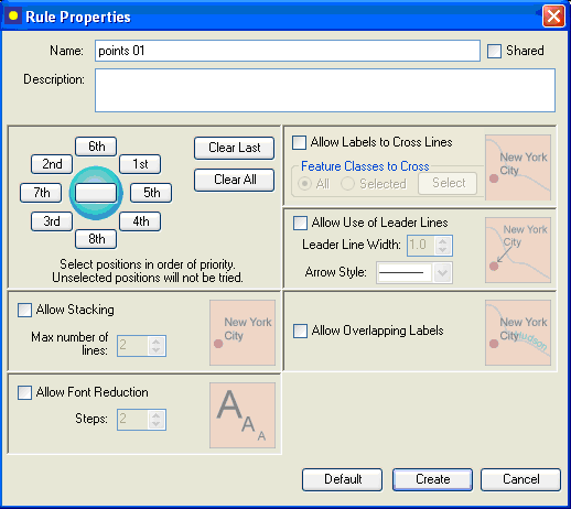
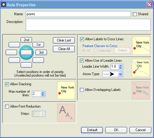
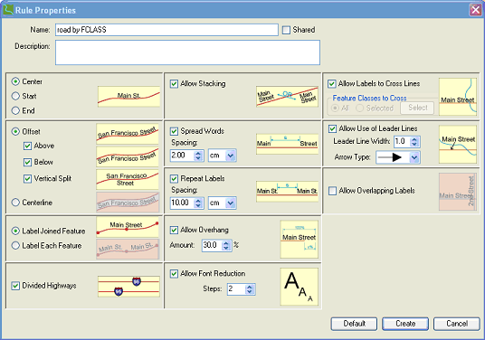
The point-feature placement rules can be set by selecting point-feature type layer(s) and clicking on the Rule button in the main screen of Label Manager. This will bring up the dialog shown below.
Users can either select the Default rules, or define rules for themselves and click the Create button.
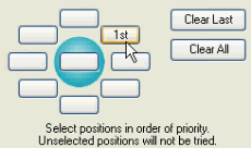
The Rule Properties dialog offers the following options:
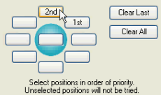
1. Selecting the positions around the point feature: the numbers 1st, 2nd, 3rd, etc. indicate the preferred positions where the text should be placed around the point feature located in the center. For example, in the above screen, 1st means that the text will first be positioned north-east of the point feature; if it is not successful, it will be positioned north-west of the feature (see position of “2nd”), and so on.
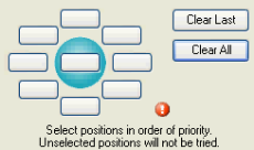
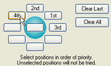
To define your own placement positions, click on Clear All, and select one-by-one your preferred text positions starting with the most preferred:
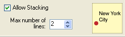
2. Allow Stacking: stacking means that feature names may be broken into a number of lines if necessary. The maximum number of lines can be specified by the user.
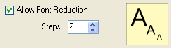
3. Allow font reduction: if this option is allowed and the label cannot be placed with the specified font size, then the font size will be reduced and labeling tried again. One step equals 0.5 points reduction and the user can set the maximum number of steps.
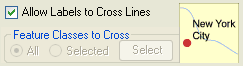
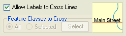
4. Allow labels to cross lines: if this option is allowed, labels may cross line features. You can allow all line and area features to be crossed or select the feature classes whose line and/or area features may be crossed.
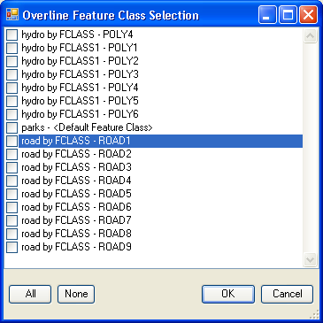
If you click the Select button, a dialog like the following will be presented, allowing you select the feature classes that may be crossed:
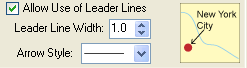
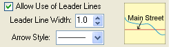
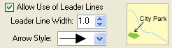
5. Allow leader lines: if this option is allowed, leader lines will be used for those point features that cannot be labeled otherwise. The arrow style can be defined by the user.
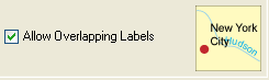
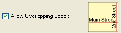
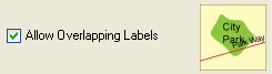
6. Allow overlapping labels: if this option is allowed, labels will be forced and may overlap with other labels.
The placement settings in the above dialog represent a sample. You may change those settings according to your requirements. After modifying the placement rules, click on Create – this will create the new rule. On subsequent modifications, the changes are made to a specific rule already defined. In the dialog, the Create button will now be replaced by an OK button. Click OK to apply these new settings to your label placement rules for the selected POINT feature layer.
3.2. Labeling rules for LINE features
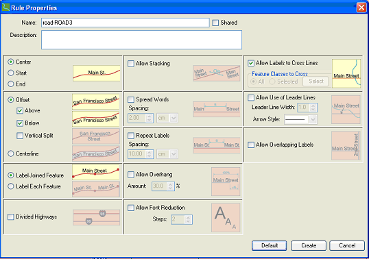
The line feature placement rules can be set by selecting a line feature type layer in the Label Manager main dialog, and clicking on the Rule button. This will bring up the Rule Properties dialog for the selected line feature layer:
Users can either accept the Default rules, or define rules for themselves and click the Create button.
The Rule Properties dialog offers the following options:
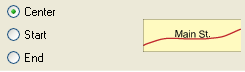
1. Text positioning along the line feature: selectable values are Center, Start, and End. Specifies where the label should be placed along the line feature.
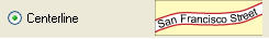
2. Offset: specifies the possible vertical positions where the text can be placed. Selectable options are Above, Below, Vertical Split, or Centerline.
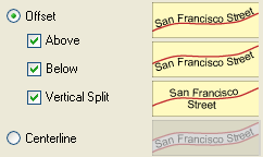
The Centerline style is used for cased (European-style) placement, as well as for road shield placement.

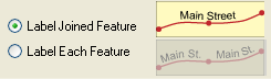
3. Label joined features: line features may consist of several segments because of digitization errors. In reality, however, those segments represent a single feature. These segments can be joined and either labeled jointly or treated as different features.
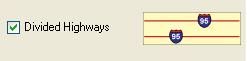
4. Label divided highways: if this option is allowed, divided highways will be labeled with one symbol only, provided that the roads are parallel and close to each other. The features must belong to the same feature class and have identical label text.
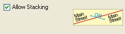
5. Allow stacking: if this option is allowed, labels may be broken up into two lines.
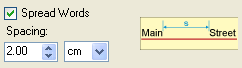
6. Spread words: names may be spread along the feature with spacing defined by the user to emphasize the extent (length) of the feature.
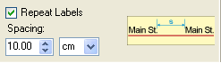
7. Repeat labels: a useful feature for long line features.
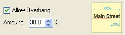
8. Allow overhang: if allowed, the name of the feature may extend beyond the lengths of the line feature. It is a useful feature for very short line features, the names of which would be impossible to place without overhang.
9. Allow font reduction:if this option is allowed and the label cannot be placed with the specified font size, then the font size will be reduced and labeling tried again. One step equals 0.5 points reduction and the user can set the maximum number of steps.
10. Allow labels to cross lines: if this option is allowed, labels may cross line features. You can allow all line and area features to be crossed or select the feature classes whose line and/or area features may be crossed.
If you click the Select button, a dialog like the following will be presented, allowing you select the feature classes that may be crossed:
11. Allow leader lines: if this option is allowed, leader lines will be used for those line features that cannot be labeled otherwise. The arrow style can be defined by the user.
12. Allow overlapping labels: if this option is allowed, labels will be forced and may overlap with other labels.
The placement settings in the dialog below represent a sample. You may change those settings according to your requirements.
After modifying the placement rules, click Create– this will create the new rule. On subsequent modifications, the changes are made to a specific rule already defined. In the dialog, the Create button will now be replaced by an OK button. Click OK to apply these new settings to your label placement rules for the selected LINE feature layer.
3.3. Labeling rules for AREA features
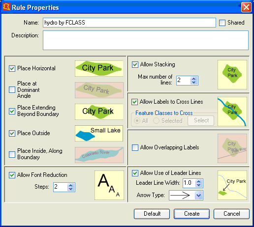
The area feature placement rules can be set by selecting an area feature type layer in the Label Manager main dialog, and clicking on the Rule button. This will bring up the Rule Properties dialog for the selected area feature layer:
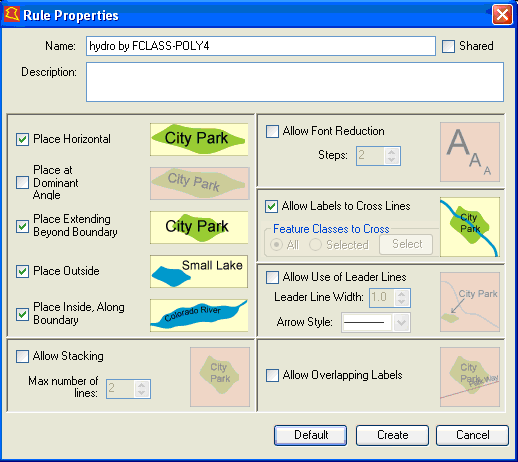
Users can either accept the Default rules, or define rules for themselves and click the Create button.
The Rule Properties dialog offers the following options:
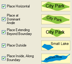
1. Text positioning for the area feature: selectable values are Horizontal, Dominant Angle, Extending Beyond Boundary, Place Outside, and Place Inside Along Boundary. The pictograms are descriptive of each capability.
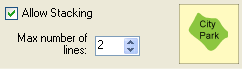
2. Allow stacking: if this option is allowed, labels may be broken up into two lines.
3. Allow font reduction:if this option is allowed and the label cannot be placed with the specified font size, then the font size will be reduced and labeling tried again. One step equals 0.5 points reduction and the user can set the maximum number of steps.
4. Allow labels to cross lines: if this option is allowed, labels may cross line features. You can allow all line and area features to be crossed or select the feature classes whose line and/or area features may be crossed.
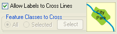
If you click the Select button, a dialog like the following will be presented, allowing you select the feature classes that may be crossed:
5. Allow leader lines: if this option is allowed, leader lines will be used for those line features that cannot be labeled otherwise. The arrow style can be defined by the user.
6. Allow overlapping labels: if this option is allowed, labels will be forced and may overlap with other labels.
The placement settings in the dialog below represent a sample.
You may change those settings according to your requirements.After modifying the placement rules, click Create– this will create the new rule. On subsequent modifications, the changes are made to a specific rule already defined. In the dialog, the Create button will now be replaced by an OK button. Click OK to apply these new settings to your label placement rules for the selected AREA feature layer.
4. The rule repository
By default all the rules and style parameters are saved in the mapworkspace. To share the rules between map workspaces and also among users, the rules need to be stored as Shared in the Shared Rules folder.
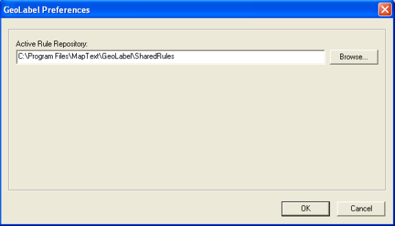
The rule repository is a directory in the file system, where the user can store placement rules to be shared. By default the location is <Installation Folder>\SharedRulesbut the user can select any other directory.
Those rules can be easily shared between different mapworkspaces and different users. There can be more than one repository, but there is only one active repository at a time. The user can switch between repositories using theGeoLabel Pro > Preferences > Active rule repository option:
GeoLabel Pro comes pre-configured with a standard rule repository located in <GeoLabel Pro installation folder>\SharedRules folder. It’s preloaded with standard rules that help with common labeling situations. This repository is loaded by default at LRM startup.
4.1. Sharing rules
The example below illustrates how to set up a shared rule for point feature label placement. After clicking on the Rule button for a point layer (1), click the Shared checkbox (2) and give an optional description of the rule. Then define the rule using the GUI options and click OK (3). Note: When the rule is defined for the first time for a layer, the button Create will appear instead of OK.
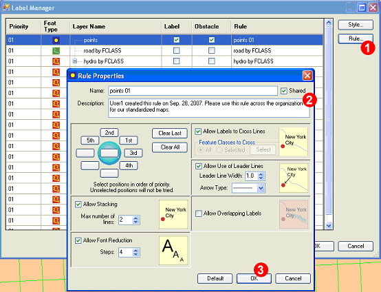
After this the name of the rule in the Rule column of the Label Manager will appear as points 01 (shared).
The user can manipulate the rules stored in the repository - the following actions are supported:
- Adding a new shared rule
The user can add a new rule to the repository by checking GeoLabel Pro > Properties > Rule > Share checkbox in the rule properties dialog – the rule is referenced from the map workspace. The rule is stored in the active rule repository when the user closes Label Rule Manager by clicking OK button.
- Modifying an existing shared rules
The user can modify existing rule by opening the map workspace (which is using the rule to be modified) and going to Rule dialog to modify the properties. Once done, the user can save the modifications to the rule repository by clicking OK in the Label Rule Manager.
- Removing a shared rule
The rule can be removed only by removing the file from the folder outside of GeoLabel Pro.
- Sharing rules between different machines
The rules can be shared between different machines by sharing the A. by copying the rule file from the repository of the current machine to the repository of the new machine, and (B) by sharing the rule repository folder accessible across the network. folder where the repository is located and setting GeoLabel Pro > Preferences > Active rule repository to this folder.
- Moving a map workspace between machines
If the map workspace is moved between machines, the user must manually move all the shared rule files used by this map workspace or share the rule repository as described in the previous point.
If GeoLabel Pro cannot find the referenced rule, then the default settings are used for affected feature layer and the user is responsible for correcting missing references. Affected feature layers are marked with red in the Label Rule Manager and the tooltip shows missing rule name.
5. Building expressions
5.1. Operators
‘+’ operator
This operator is used for combining values of 2 attributes to form a single string without any white space between them. (If both operands are numerical, it will form their arithmetic sum.)
Example: Height + “Feet”
For the element with FeatID = 1, the text string would be “1000.00Feet”
‘++’ operator
This operator is like the + operator, except that it inserts a single white space between the 2 elements being joined.
Example: Height ++ “Feet”
This yields the text string “1000.00 Feet”
‘-‘ operator
Computes the arithmetic difference if both operands are numerical; else null.
‘&’ operator
This operator will combine the values of 2 attributes to form a single string with the restriction that both of the attributes must be non-blank strings. It will form the result string without any white space between the 2 values.
Example: Height & “Feet”
For FeatID = 1, this yields “1000.00Feet”.
For FeatID = 3, this yields a blank “”.
‘&&’ operator
This operator is like the & operator, except that it automatically introduces a single white space between the 2 elements being joined while still ensuring that the 2 elements are non-blank strings.
Example: Name && Type
For FeatID = 1, this yields “MapText Office”.
For FeatID = 2, this yields a blank “”.
For FeatID = 3, this yields a blank “”.
‘|’ operator
This operator is used for specifying an alternate attribute (or value) to be used for the text string if the current value being formed is a blank string.
Example: Name | Type
For FeatID = 1, this yields “MapText”.
For FeatID = 2, this yields “AllState Insurance”.
For FeatID = 3, this yields “Pub”.
‘(’ and ‘)’ operator pair
This operator pair is used for grouping elements and operators together so that they will be treated as a single element for other operators or text processing commands.
Example: (Name | Type)++ ((Height && “Feet”) | (Elev && “Miles”))
If you want to form a complex text string that will list the name (or the type) of the feature and its height in feet (or its elevation in miles) separated by a space, then specify it as:
For FeatID = 1, this yields “MapText 1000.00 Feet”.
For FeatID = 2, this yields “AllState Insurance 2500.00 Feet”.
For FeatID = 3, this yields “Pub 23.44 Miles”.
MOD operator
Yields the modulus of the two operands. Both operands must be integers, and the modulus is the remainder generated by dividing the first by the second operand.
NOT … AND … OR … THEN … ELSE
These operators conform to standard usage for logical expressions. Note that ‘IF’ is optional. It is implied at the beginning of a logical expression containing the THEN operator.
5.2. Commands
ALPHA[<field>]
This command removes all numeric characters (0-9) from the value of the element.
Example: ALPHA[RD]
For FeatID = 1, this yields “Ihwy ”.
For FeatID = 2, this yields “Shwy ”.
For FeatID = 3, this yields “US Hwy ”.
CONTAIN
This command allows you to compare an operand to a string enclosed in quotes to determine whether the operand contains the string.
Example: NAME CONTAIN “Insurance” THEN “Insurance Company” ELSE “”
(If the operand NAME contains the word “Insurance”, then the result of the entire logical expression is “Insurance Company.” Otherwise it is blank.)
DEC[<field>, n]
Use this command to trim the floating-point value of an element’s string to n decimal places. It should be used for numerical fields only. The value will not be rounded off but simply truncated to the number of places specified.
Example:
|
FeatID |
ELEV |
|
1 |
25.56 |
|
2 |
26.71 |
|
3 |
23.44 |
If you want to form the text string indicating the elevation of each feature (with precision to a single decimal digit), then it can be specified as:
DEC [ELEV ,1]
For the element with
For FeatID = 1, this yields “25.5”.
For FeatID = 2, this yields “26.7”.
For FeatID = 3, this yields “23.4”.
FLOAT[<field>]
Use this command to remove all non-numeric characters (but not the decimal point) from the value of the element to form a floating-point value. If multiple decimal points are present, the first is retained and all others are discarded.
|
FeatID |
NAME-LOC |
|
1 |
MapText @ 25.56 miles |
|
2 |
AllState Insurance @ 26.71 miles |
|
3 |
Pub @ 23.44 miles |
Example: FLOAT[Name-Loc]
For FeatID = 1, this yields “25.56”.
For FeatID = 2, this yields “26.71”.
For FeatID = 3, this yields “23.44”.
INRANGE[<field>]
With this command you can compare an operand to a numerical range inclosed in square brackets to determine whether the operand is within the range, including the bounding numbers.
Example: ELEV INRANGE [24,27] THEN “ElevationA” ELSE “ElevationB”
(The value of the field ELEV is compared with the range >=24 to <=27 and if it falls within it, the result is “ElevationA”; otherwise it is “ElevationB”)
LCASE[<field>]
Converts the characters in the value of the element to all-lowercase.
Example: LCASE[Name] ++ Type
For FeatID = 1, this yields “maptext Office”.
For FeatID = 2, this yields “allstate insurance”.
For FeatID = 3, this yields “Pub”.
LENGTH[<field>]
This operator returns the number of characters in an expression.
Example: LENGTH[ParcelNumber]
LIKE
With this command, you can determine whether an operand is structurally similar to the string of a specified field.
Example: ROAD LIKE “IHwy *” THENNUM[ROAD] ELSE “”
(If ROAD contains the string “IHwy” followed by some unspecified characters
(e.g., IHwy. 95), then this logical expression will yield the numerical part only (“95”).
Otherwise it will be null.
LOOKUP[<field>, filename, C1, C2, {“delimiter”}]
Use this command to define a lookup table for the element so that the value from the look-up table is used for placement instead of the value itself. The look-up table is specified by the filename. C1 specifies the column number that will contain the actual value of the element (from the attribute tables). C2 specifies the column number that will contain the look-up text that is the result of this command. By default the delimiter is assumed to be a tab. However, a different delimiter can be specified within double quotes. If no path is provided for the look-up filename, it is assumed to exist in the map directory.
Example 1:
Feature Attribute Table
|
FeatID |
CODE |
|
1 |
Y |
|
2 |
Z |
|
3 |
X |
Lookup table “codetable.txt”
|
X: 23.56: White: Miles |
|
Y: 45.76: Blue: Feet |
|
Z: 23.89: Red: Miles |
If the user wants to form the text string from the attribute CODE using the look-up values in column 3 of the look-up table “codetable.txt” (which has colon-separated columns), then it can be specified as:
LOOKUP[code, codetable.txt, 1, 3, “:”]
For FeatID = 1, this yields “Blue”.
For FeatID = 2, this yields “Red”.
For FeatID = 3, this yields “White”.
Special Notes:
(1) If a particular value of the element cannot be found in the column specified using C1, then the result string is the value of the element. For example if the value X could not be found in the first column, then the TextString would have received the value X.
(2) When a value is not found in the column specified, changing a system setting can modify the type of result obtained. You can get the result either as a blank string or as an error message written to the logfile.
MEMBEROF
With this command you can compare an operand to a set of strings enclosed in quotes and surrounded by curly brackets. If the operand is equal to any of the strings, the result is logically True. Otherwise it is logically False.
Example: NAME MEMBEROF { “Office”, “Center”, “Hotel” } THEN “BuildingA”
ELSE “BuildingB”
If NAME is “Office”, the result is “Building A”
If NAME is “Home”, the result is “BuildingB”.
NUM[<field>]
Use this command to remove all non-numeric characters from the value of the element and concatenate the numeric characters to form an integer.
Example: NUM[RD]
For FeatID = 1, this yields “95”.
For FeatID = 2, this yields “9”.
For FeatID = 3, this yields “1”.
OMIT[<field>, “s1”, “s2”,..., “sn”]
Use this command to ignore particular values by specifying them as a list of comma-separated values.
|
FeatID |
RD-NAME |
|
1 |
South Main St |
|
2 |
Unknown |
|
3 |
Washington Blvd |
|
4 |
Ramp |
Example: OMIT[RD-NAME, “Unknown”, “Ramp”]
For FeatID = 1, this yields “South Main St”.
For FeatID = 2, this yields “”.
For FeatID = 3, this yields “Washington Blvd”.
For FeatID = 4, this yields “”.
PCASE[<field>]
Converts the characters in the value of the element to all-proper case (initial letter in capitals).
Example: PCASE[Name] ++ Type
For FeatID = 1, this yields “Maptext Office”.
For FeatID = 2, this yields “Allstate Insurance”.
For FeatID = 3, this yields “Pub”.
REMOVE[<field>, “string to remove>”, …, “string to remove>”]
With this command you can remove one or more specified strings from a given operand.
Example: REMOVE[RD, “Hwy”]
Thus if a field RD contains an entry “IHwy” as well as the number 95, the result will be “I95”.
REPLACE [<field>, “<string to replace>”, “<new string>” ; … ; “<string to replace>”, “<new string>”]
This operator will search the expression on which it is operating for the strings to replace. When a match is found, the string to replace is replaced with the paired new string. Note placement of commas and semicolons.
Example: if the NAME field contains “Street” or “Avenue”, we can replace these with “St” or “Ave”. The following would do this:
REPLACE [<NAME>, “Street”, ”St” ; ”Avenue”, ”Ave”]
Note that case matters during the string search.
ROUND[<field, <n>]
With this command you can round-off an operand to the nearest decimal place. The ‘n’ argument, which must be equal to or greater than 0, specifies the decimal place.
Example: ROUND [ELEV, 0]
For ELEV = 215.37, this yields 215
For ELEV = 215.59, this yields 216
SUBSTRING[<field>, <start>, <length>]
With this command you can extract a substring from the input operand by specifying the starting character within the string and the number of characters from the starting character.
If the start argument is positive, it refers to a count from left to right. If negative, the count is from right to left. The length argument is always counted from left to right.
Example: If the field NAME contains the string “Major Road”, then
SUBSTRING[NAME, 1, 5] would extract the string “Major”,
SUBSTRING[NAME, 7, 4] would extract the string “Road”, and
SUBSTRING[NAME, -4, 4 ] would extract the string “Road”
TOKEN[<field>, “string”, n]
Use this command to extract a specific section from the value of the element that is sub-divided, based on the string you provide. The tokenizing string must be given in double quotes, and the number n specifies the token. If the specified token does not exist, the result will be blank. The token number can also be negative, which will cause the tokens to be extracted starting from the right side of the value of the element.
|
FeatID |
NAME-LOC |
|
1 |
MapText @ 25.56 miles |
|
2 |
AllState Insurance @ 26.71 miles |
|
3 |
Pub @ 23.44 miles |
Example 1: TOKEN[Name-Loc, “@”, 1]
For FeatID = 1, this yields “MapText ”.
For FeatID = 2, this yields “AllState Insurance ”.
For FeatID = 3, this yields “Pub ”.
The result string in the above example will have the trailing white space. Use the TRIM command to remove the white space.
|
FeatID |
NAME-LOC |
|
1 |
MapText @ Plainsboro, 25.56 miles |
|
2 |
AllState Insurance @ Princeton, 26.71 miles |
|
3 |
Pub @ New Brunswick, 23.44 miles |
If you want to form the text string indicating the city location of each feature (which is stored as a part of the Name-Loc attribute), then specify it as:
Example 2: TOKEN[TOKEN[Name-Loc, “,”, 1], “@”, –1]
or TOKEN[TOKEN[Name-Loc, “,”, 1], “@”, 2]
For FeatID = 1, this yields “ Plainsboro”.
For FeatID = 2, this yields “ Princeton”.
For FeatID = 3, this yields “ New Brunswick”.
In the above example, we first tokenize the entire element using a comma as the token string. Then we tokenize the result using “@” as the token string. The result string in the above example will have a leading white space. You can use the TRIM command to get rid of the while space. However if we include the white space in the tokenizing string, i.e., use “@ “ instead of “@”, then we will get the result without any leading spaces.
TRIM[<field>, “string”, … , “string”, {L, R, B}]
This command allows you to remove a string of characters from either side of the element. A list of strings can be given for trimming off text from either side of the element. As each string is trimmed from the element, a new part of the element is exposed that can be tested for the existence of more strings to trim. The last argument indicates whether trimming should take place on the left (L) side of the element, on the right (R) side of the element, or on both (B) sides of the element.
Example:
|
FeatID |
NAME |
|
1 |
Main Street |
|
2 |
Forest Park Terrace |
|
3 |
Drake Avenue |
If you want to remove the part of the NAME attribute that contains the type of road, then provide the following TextString:
TRIM[NAME, “Street”, “Terrace”, “Avenue”, R]
Thus for the element with
For FeatID = 1, this yields “Main ”.
For FeatID = 2, this yields “Forest Park ”
For FeatID = 3, this yields “Drake ”
UCASE[<field>]
This command converts the characters in the value of the element to all uppercase.
Example: UCASE[Name] ++ Type
For FeatID = 1, this yields “MAPTEXT Office”.
For FeatID = 2, this yields “ALLSTATE INSURANCE”.