Outputs circular sectors of influence for point features that have directions defined by azimuths (degrees clockwise from North).
This transformer creates a number of sectors for each set of point features (collectively called a site), depending on each point’s direction of influence. Each sector fans out from the center point (called site point) of the site it belongs to, and has a user-defined radius. Sectors generated for a site will not overlap each other, but they may overlap with sectors of other sites. If you want to avoid overlaps between different sites, use the VoronoiCellGenerator transformer instead.
Input Ports
This transformer only accepts points as input. All other geometries are rejected.
2D points are completely supported, but 3D points may result in incorrect Azimuth lines. If you have points with z values, try removing the z values by using the 2DForcer transformer first.
Output Ports
Resulting sectors are output via this port. The sectors are output as rich geometry polygons with arcs or ellipses.
These are lines showing the direction each input point is facing (or influencing). Each line starts from an input point, has a length equal to its input radius, and goes to the direction of its input azimuth.
For each site, a point is created with coordinates that are the average of the coordinates of all points accepted for that sector. This point is the center of all sectors generated for a site.
If a Sector Name Attribute is specified and there are points with the same sector and site names, only the first point meeting all requirements is considered for creating sectors and the rest are output via this port.
Upon entering transformer, if a point is found to be farther from any of the other points in its site than the specified Maximum Distance Between Site Points, it will be dropped from sector generation and output from this port.
These are output points that are missing or have invalid values for required attributes.
Non-point features are left untouched and output via this port.
Parameters
Transformer
This option allows you to select attributes that define which groups to form. Each set of features that have the same value for all of these attributes will be processed as an independent group.
Note: The Group By parameter cannot be used if the Input is Ordered by Site Name parameter is set to Yes.
Note: How parallel processing works with FME: see About Parallel Processing for detailed information.
This parameter determines whether or not the transformer should perform the work across parallel processes. If it is enabled, a process will be launched for each group specified by the Group By parameter.
Parallel Processing Levels
For example, on a quad-core machine, minimal parallelism will result in two simultaneous FME processes. Extreme parallelism on an 8-core machine would result in 16 simultaneous processes.
You can experiment with this feature and view the information in the Windows Task Manager and the Workbench Log window.
Yes: This transformer will process input groups in order. Changes on the value of the Group By parameter on the input stream will trigger batch processing on the currently accumulating group. This will improve overall speed if groups are large/complex, but could cause undesired behavior if input groups are not truly ordered.
No: This is the default behavior. Processing will only occur in this transformer once all input is present.
Parameters
This is the attribute that determines the site to which an input point belongs.
The direction each input point faces (or influences). The Azimuth Attribute value is measured in degrees clockwise from North.
For an Azimuth Attribute value to be valid, it should be nonnegative and less than 360.
If a Sector Name Attribute is specified, then each feature entering the SectorGenerator will be checked to see if its sector name is already in use within its site. If it is, then it will be output on the ExtraPoints port.
Radius of influence for each sector. This determines radius of each sector in a site. It is also the length of each input point’s Azimuth Line.
The maximum distance a point can have from any of the other points in its site and still be considered in sector creation. Points are considered in the order they enter the transformer, with each new point tested against all other points already accepted as a part of its site.
If a nonconstant value is specified for this parameter (e.g., an attribute value, which may differ from feature to feature), then when comparing the distance between two features, the maximum distance will be calculated from the feature that entered the transformer earlier.
If this option is set to Yes, the SectorGenerator assumes that each site’s input features occur consecutively in its input. Processing will occur on each site as it is input, instead of waiting for all features before starting. Setting this parameter to Yes can conserve the use of resources.
Note: Note that setting this parameter to Yes will cause the translation to fail if any Group By attributes are specified.
Example
In the telecommunications industry, directional antennas are used in conjunction with each other for better coverage and stronger signal reception. These antennas each cover a sector of a complete circle that an antenna tower covers, with some areas of overlap between each two sectors.
This transformer can be used to determine the “Nominal” (assuming a whole circle is covered and there are no overlaps between sectors in one site) coverage field of directional antennas and receivers.
Input points and their azimuth values are received:
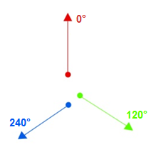
A center point is created for each site:
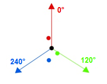
Note: Please note that after this step, the locations of input points play no part in the generation of sectors, and the values that determine sectors are the input points’ azimuths and radii.
Note: In this diagram, azimuth lines are drawn from the center point for a better visual understanding of how this transformer computes sectors.
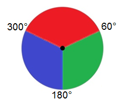
Polygon sectors are generated. The sector corresponding to each point will span an area determined by the radius set and
(The point's azimuth + adjacent azimuth (in degrees))/2
This means that each point's azimuth will be in the interior of its generated sector, and the boundary segment between sectors will bisect the angle between the two sector point's azimuth values. Resulting sectors will look like this:
Editing Transformer Parameters
Using a set of menu options, transformer parameters can be assigned by referencing other elements in the workspace. More advanced functions, such as an advanced editor and an arithmetic editor, are also available in some transformers. To access a menu of these options, click  beside the applicable parameter. For more information, see Transformer Parameter Menu Options.
Transformer Categories
FME Licensing Level
FME Professional edition and above
Search FME Knowledge Center
Search for samples and information about this transformer on the FME Knowledge Center.
Tags Keywords: "cellular phone" phone tower antenna coverage "cell phone" cel