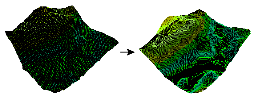
Constructs a Delaunay triangulation based on input points and breaklines. Contour lines are then generated from the triangulation.
Input
These input features may be 2D or 3D. Other than points, lines and area geometries, they may also be raster, point cloud, and aggregate geometries.
2D features will be forced to 3D by adding a z value of 0. In most cases, all points extracted from this port will be found in the vertex pool of the underlying surface model. A minimum of 3 unique points are required to construct a surface model. Points with duplicate x and y values will be dropped.
These input features may be 2D or 3D, and may reside inside an aggregate structure.
2D features will be forced to 3D by adding a z value of 0. Breakline edges will be found in the edge pool of the underlying surface model. Sometimes, a breakline edge will be split up to allow an optimal triangulation of the surface model. Points with duplicate x and y values will be dropped.
Output
This output port produces contour lines. Each contour is 2D or 3D depending on Output Contour Dimension, and stores its elevation in the attribute specified in Output Elevation Attribute. If contours are 3D, then their z values are equivalent to their elevation attribute values.
Tip: The parameter Conflict Resolution can filter out a subset of input Points/Lines to ensure a well-constructed surface model.
Parameters
Transformer
This parameter allows groups to be formed by attribute values. Zero or more attributes may be specified.
Input features with the same attribute values are placed into the same group. The transformer then operates independently on each group of input features.
If this parameter is left blank, the transformer will treat the entire set of input features as one group.
Note: How parallel processing works with FME: see About Parallel Processing for detailed information.
This parameter determines whether or not the transformer should perform the work across parallel processes. If it is enabled, a process will be launched for each group specified by the Group By parameter.
Parallel Processing Levels
For example, on a quad-core machine, minimal parallelism will result in two simultaneous FME processes. Extreme parallelism on an 8-core machine would result in 16 simultaneous processes.
You can experiment with this feature and view the information in the Windows Task Manager and the Workbench Log window.
Yes: This transformer will process input groups in order. Changes on the value of the Group By parameter on the input stream will trigger batch processing on the currently accumulating group. This will improve overall speed if groups are large/complex, but could cause undesired behavior if input groups are not truly ordered.
No: This is the default behavior. Processing will only occur in this transformer once all input is present.
Parameters
This parameter is used to determine which input points to add to the surface model as vertices. Specifying a value of 0 turns off vertex filtering.
Tip: A larger value will speed up surface model construction. The larger the value, the more input points will be filtered out. For input files with millions – or even billions – of points, it becomes essential to increase this value.
When a positive value for surface tolerance is specified, it works as follows. For each vertex that is being added to the model:
- If the x,y location is outside the 2D convex hull of the existing surface model, it is added to the model.
- If the x,y location is inside the 2D convex hull of the existing surface model:
- The difference between the z value from the existing surface model and the z value of the vertex is calculated.
- This difference is compared to the surface model tolerance.
- The vertex is only added to the surface model if the difference is greater than the surface tolerance; otherwise, the vertex is discarded.
This parameter specifies the name of an elevation attribute for the output ports Contours and DEMPoints, when these output ports exist on the transformer.
This parameter specifies the elevation separation of the output contours.
This parameter specifies whether the output contours are 2D or 3D. 2D contours are equivalent to 3D contours, except that the z coordinates are dropped.
Tip: When the input dataset is large enough, setting this parameter to 2D will result in a visible performance improvement.
This parameter controls whether input points on the contour interval are dropped, or perturbed. Not dropping or perturbing these points would result in topologically invalid contours.
- Perturb Input Points on Contour Interval: Contours are negatively offset in the z direction. The perturbation amount is 1% of the contour interval.
- Remove Input Points on Contour Interval: Input points on the contour interval are not added to the underlying surface model.
Example

FME Licensing Level
FME Professional edition and above
Editing Transformer Parameters
Using a set of menu options, transformer parameters can be assigned by referencing other elements in the workspace. More advanced functions, such as an advanced editor and an arithmetic editor, are also available in some transformers. To access a menu of these options, click  beside the applicable parameter. For more information, see Transformer Parameter Menu Options.
Transformer Categories
Search FME Knowledge Center
Search for samples and information about this transformer on the FME Knowledge Center.
Tags Keywords: pointcloud