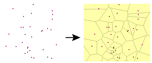
Generates a Voronoi diagram or Thiessen polygon. A Voronoi diagram is a set of polygons that represent proximity information about a set of input points. Each polygon in the diagram defines the area of space that is closest to a particular input point.
Note: If a Voronoi diagram is to be made from points with elevations, and you want to add additional breakline and tolerance options, consider using the SurfaceModeller transformer.
Input Ports
The extent of the Voronoi diagram is guaranteed to cover the bounding box of all the input Point features. At least three points must be input.
Features input to the optional MinimumVoronoiExtent port will expand the extent of the resulting diagram to include their bounding box. This provides a way of extending the bounds of the diagram well past the extent of the input points.
Parameters
Transformer
This parameter allows groups to be formed by attribute values. Zero or more attributes may be specified.
Input features with the same attribute values are placed into the same group. The transformer then operates independently on each group of input features.
If this parameter is left blank, the transformer will treat the entire set of input features as one group.
Note: How parallel processing works with FME: see About Parallel Processing for detailed information.
This parameter determines whether or not the transformer should perform the work across parallel processes. If it is enabled, a process will be launched for each group specified by the Group By parameter.
Parallel Processing Levels
For example, on a quad-core machine, minimal parallelism will result in two simultaneous FME processes. Extreme parallelism on an 8-core machine would result in 16 simultaneous processes.
You can experiment with this feature and view the information in the Windows Task Manager and the Workbench Log window.
Yes: This transformer will process input groups in order. Changes on the value of the Group By parameter on the input stream will trigger batch processing on the currently accumulating group. This will improve overall speed if groups are large/complex, but could cause undesired behavior if input groups are not truly ordered.
No: This is the default behavior. Processing will only occur in this transformer once all input is present.
Parameters
If this parameter is set to Yes, which is the default, attributes from input points will be preserved on the output polygons.
If specified, this value limits the radius of the output polygons. This provides a way of generating a region of influence around each point.
Attribute Accumulation
If Drop Incoming Attributes is chosen, the output feature will not preserve any input attributes. If Merge Incoming Attributes is chosen, the output feature will merge all input attributes. If Get Attributes from One Representative Feature is chosen, the output feature will get attributes from only one input feature.
If checked, specify a name for a list attribute that is generated from incoming features.
Example

FME Licensing Level
FME Professional edition and above
Editing Transformer Parameters
Using a set of menu options, transformer parameters can be assigned by referencing other elements in the workspace. More advanced functions, such as an advanced editor and an arithmetic editor, are also available in some transformers. To access a menu of these options, click  beside the applicable parameter. For more information, see Transformer Parameter Menu Options.
Transformer Categories
Search FME Knowledge Center
Search for samples and information about this transformer on the FME Knowledge Center.
Tags Keywords: MBR "minimum bounding rectangle" VoronoiDiagram