Performs a geometric clipping operation.
This transformer takes a number of clip boundaries (Clippers) and a number of features to be clipped (Clippees). The output is split into two groups: the parts of the Clippees that are within the clip boundaries, and the parts of the Clippees that are not within the clip boundaries. The Clippees that intersect the clip boundaries will be cut into multiple sections (along the clip boundaries), and then each section will be added to the appropriate group. The Clippees that do not intersect are added directly to the appropriate group, and are output without modification.
Input Ports
The features routed into the transformer via the Clipper port identify the area against which all Clippee features are processed. The Clipper can consist of any area features (polygons, donuts, or aggregate polygons/donuts). The Clipper can also be a solid or multi-solid if the Clippee input consists of solids, points, point clouds, or aggregates of these geometries. Any invalid clipping features that are encountered will be logged with a warning and discarded.
Features to be clipped enter via the Clippee port.
Output Ports
Clippee features that are completely within the Clipper, and Clippee features that intersect the Clipper which were broken up into pieces. Those pieces that are on the inside of the Clipper are output via this port.
Clippee features completely outside of the Clipper are output via the Outside port, and Clippee features that intersect the Clipper which were broken up into pieces. Those pieces that are outside the clipping area are output via the this port.
Invalid Clipper features (that is, non-polygon features) as well as invalid Clippee features (that is, features with no geometry) are output via the <Rejected> port.
Rejected features will have an fme_rejection_code attribute with one of the following values: EXTRA_CLIPPER_FEATURE, INVALID_CLIPPER_GEOMETRY_TYPE.
Parameters
Transformers
If Group By attributes are selected, features with the same values in the Group By attributes are placed into the same set, and clipping occurs in each set independent of other sets.
Parameters
- Single Clipper: Only a single Clipper feature will be used.
- Multiple Clippers: All Clipper features will be used.
- Clippers First: The Clipper assumes that all Clipper features will enter the transformer before any Clippee features. Any further Clipper features that arrive after the first Clippee will be logged with a warning and discarded.
This attribute (if specified) will be added with a value of yes to any features output via either the Inside or Outside port which were cut by the transformer, and a value of no to any output features which were not changed by the transformer.
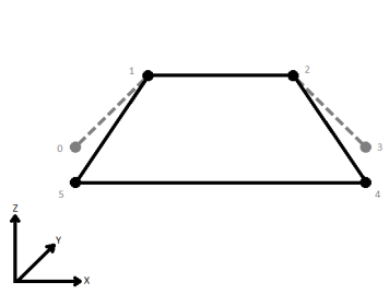
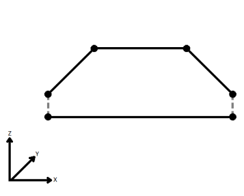
When viewed in 2D (ignoring Z), a path (which may define the border of a polygon) may appear to be closed as shown in the left figure below. This same path, when viewed in 3D, may appear to be open as shown in the right figure below.
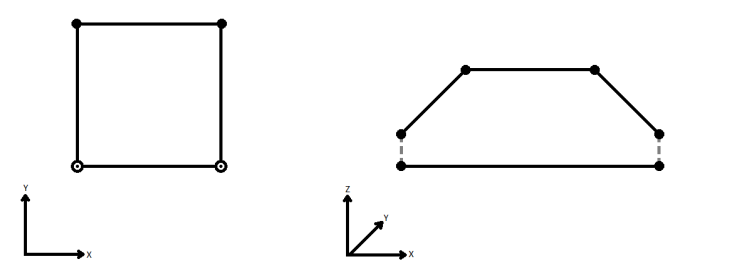
To specify how (and if) paths should be closed in 3D, select one of the listed modes.
| Mode | Description | Example |
|---|---|---|
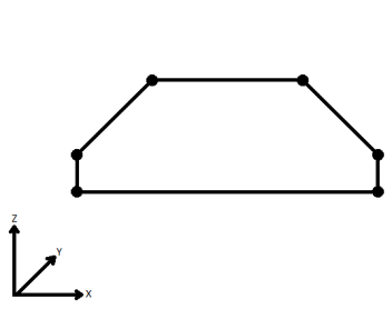
| Extend | The Curve is extended so that all vertices are left at their original location. |
|
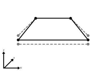
| Average | Subsequent vertices that are not connected, but share an x and a y value are combined into one vertex, whose Z value is the average of the original two. |
|
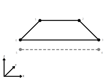
| First Wins | Subsequent vertices that are not connected, but share an x and a y value are combined into one vertex, whose Z value is taken from the first encountered vertex. |
|
| Last Wins | Subsequent vertices that are not connected, but share an x and a y value are combined into one vertex, whose Z value is taken from the last encountered vertex. |
|
| Ignore | Z values are ignored. No change is made to the way the nodes are connected. |
|
If set to Yes, then contiguous lines that constitute the boundary of the output features will be left as separate segments in a path. The default is No, which means that such lines will be joined into longer lines in the output unless they have different properties (e.g. traits, measures, and geometry name).
Vector Processing
This parameter directs what action should be taken with Clippee features that lie entirely on the boundary of the clipper.
- Treat as Inside: These features that lie on the boundary are output via the Inside port.
- Treat as Outside: These features that lie on the boundary are output via the Outside port.
- Treat as Inside and Outside: Points and line segments on the boundary are duplicated and output as both Inside and Outside.
If the Create Aggregates parameter is No, then features that are clipped into multiple parts will not be aggregated, but rather each part will be output as a separate feature.
Raster Processing
If this parameter is set to No, the Inside rasters which were clipped will be equal to the intersections of the clippers and clippees. Otherwise, the intersections will be padded by nodata so that the extents are identical to those of the input rasters.
Merge Attributes
If the Merge Attributes parameter is enabled, attributes on the Clipper will be merged onto the Clippee as defined by the parameters within the expandable group. Otherwise, no attribute merging will take place.
If attributes on the Clipper and Clippee features share the same name, but are not geometry attributes that start with fme_, then they are deemed conflicted.
Merge Clipper: The Clippee feature will retain all of its own un-conflicted attributes, and will additionally acquire any un-conflicted attributes that the Clipper feature has. This mode will handle conflicted attributes based on the Conflict Resolution parameter.
Prefix Clipper: The Clippee feature will retain all of its own attributes. In addition, the Clippee will acquire attributes reflecting the Clipper feature’s attributes, with the name prefixed with the Prefix parameter.
Only Use Clipper: The Clippee feature will have all of its attributes removed, except geometry attributes that start with fme_. Then, all of the attributes from one (arbitrary) Clipper feature will be placed onto the Clippee.
Use Clippee: If a conflict occurs, the Clippee values will be maintained.
Use Clipper: If a conflict occurs, the values of the Clipper will be transferred onto the Clippee.
If the Accumulation Mode parameter is set to Prefix Clipper, this value will prefix attributes that are being added to the Clippee feature from the Clipper feature.
Usage Notes
- This transformer works with raster, point cloud, and vector data.
- This transformer is unaffected by raster band and palette selection.
- Clipped raster cells (i.e. those outside the clipper but part of an Inside raster) will be set to the nodata value. If a nodata value has not been set, clipped raster cells will be set to 0. To set a value for nodata, use the RasterBandNodataSetter transformer prior to the Clipper.
Example
The example below illustrates the input features on the left and the output features on the right. Both the input and output consist of a clipping boundary (1) (Clippers) in blue and the clip features (2) (Clippees) in red. The output then splits the features into two groups: Inside port and Outside port.
The Clippee features highlighted in white fall within or intersect the clipper, and these features are output to the Inside (3) port. The Clippee features that fall outside of the clipping boundary are output to the Outside (4) port.

Editing Transformer Parameters
Using a set of menu options, transformer parameters can be assigned by referencing other elements in the workspace. More advanced functions, such as an advanced editor and an arithmetic editor, are also available in some transformers. To access a menu of these options, click  beside the applicable parameter. For more information, see Transformer Parameter Menu Options.
Transformer Categories
Search FME Knowledge Center
Search for samples and information about this transformer on the FME Knowledge Center.
Tags Keywords: MBR "minimum bounding rectangle" raster grid clip clipper clippee subset extent sample bound clean conflation overshoot undershoot pointcloud