Assigns colors to incoming features.
Input Ports
Input features to be colored.
Note that features must be topologically clean if you are using the Map Coloring schemes.
Output Ports
Features with new color attributes.
Features are output through this port when the FeatureColorSetter is passed an inappropriate input type and cannot apply the chosen color scheme to the input. The two color schemes Map Coloring: Five Color and Map Coloring: N Color (Fast) will produce rejected output if the FeatureColorSetter is passed a non-polygon input.
Parameters
Mode
Fixed: Manually set a feature's pen and fill colors using the Pen Color and Fill Color parameters.
Random: Sets a random color for each incoming feature.
Random (Offset): Same as Random, but with the pen color slightly different than the fill color. This gives a good visual result.
Map Coloring: Assigns colors to areas in a coverage so that adjacent areas are output as different colors. The total number of colors used is kept as small as possible while ensuring that no two adjacent regions receive the same color.
When using the N Color (Fast) scheme, each area is colored with the first available color. Ideally, only a few colors will be used but the total number of colors is not guaranteed.
When using the Five Color scheme, a maximum of five colors will be used to color the regions.
Color Limit: Enables the Unique Color Limit parameter described below.
Attributes: Enables the Randomize By Attributes parameter described below.
When the Color Scheme is set to Random or Random (Offset) and the Randomize Based On is set to Attributes, use this parameter to group the input features based on the specified attributes. Grouped features will all be colored the same random and unique color.
If left empty while enabled, each input feature will be treated as its own group.
When the Color Scheme is set to Random or Random (Offset) and the Randomize Based On is set to Color Limit, use this parameter to set a limit on the number of unique colors randomly selected.
The limit can be set to any integer value with a lower bound of 0. If set to 0, then no bound is applied, and there will be no limit to the number of different colors used.
Parameters
When the Color Scheme is set to Fixed, use this parameter to set the pen color (fme_color).
If blank, the pen color will remain unchanged and the value of fme_color will be left as is.
The color is formatted as r,g,b, where each of r, g, and b is a number between 0 and 1.
Use this parameter to set the fill color (fme_fill_color). If blank, the fill color will remain unchanged and the value of fme_fill_color will be left as is.
The color is formatted as r,g,b, where each of r, g, and b is a number between 0 and 1.
When the Color Scheme is set to Map Coloring, this is the attribute that contains the output color code. The default is _color_id.
Colors are output to the Color ID Attribute as integers (the first color is 0, the second color is 1, etc.).
These parameters are used when the Color Scheme is set to Map Coloring.
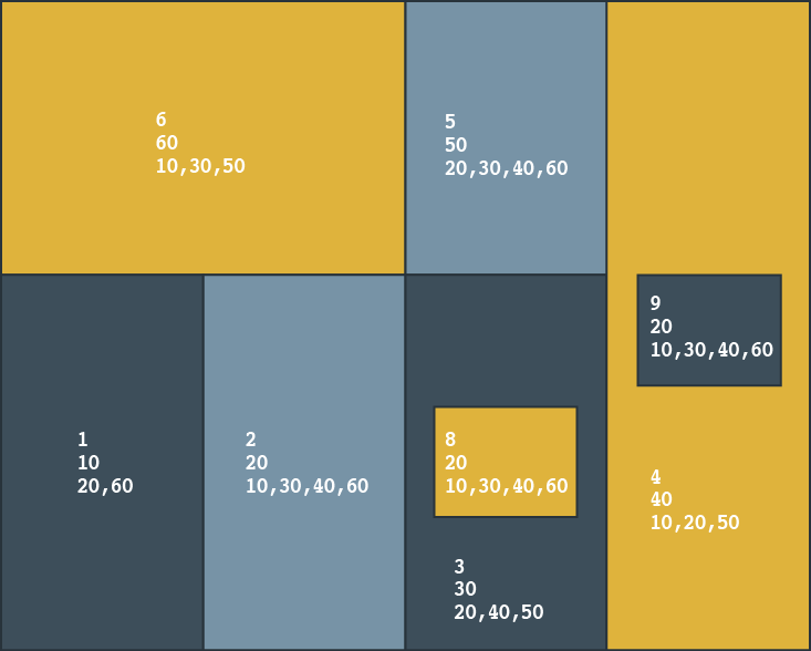
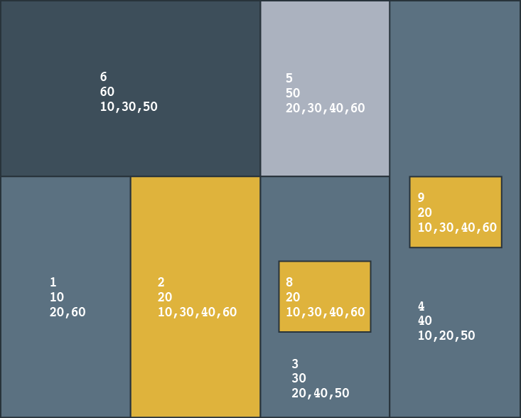
When you provide a Pre-existing Area ID Attribute and Neighbor ID Attributes for each area, you can force the relationships to follow pre-existing mappings. For example, if your data contains aggregates and you know the area to which they belong, you can define that relationship using these parameters.
This option is especially useful when the input data contains aggregates and you want to "map" pre-existing IDs to define the relationships.
Note: If these parameters are not provided, adjacencies between areas are determined geometrically, and non-polygon geometries (including aggregates and ellipses) are removed.
Area IDs must be non-negative integers, and neighbor IDs are entered as a comma-separated list.
Example
In the example below, there are unique feature counts and then IDs.

If aggregates are not important, only 3 colors are required:
| Feature | Adjacent to Areas |
|---|---|
| 2,20 | 1, 3, 6 |
| 8,20 | 3 |
| 9,20 | 4 |
If, however, ID 2,20 is treated as an aggregate, then 4 colors are required and the pre-existing ID attributes must be supplied.
| Feature | Adjacent to Areas |
|---|---|
| 20 | 10, 30, 40, 60 |
| Feature | Not Adjacent to Area |
| 20 | 50 |

- A TopologyBuilder placed before the FeatureColorSetter can help you build a list of adjacent areas.
- An AttributeFilter or another FeatureColorSetter can be used to manipulate the Color ID attribute.
Editing Transformer Parameters
Using a set of menu options, transformer parameters can be assigned by referencing other elements in the workspace. More advanced functions, such as an advanced editor and an arithmetic editor, are also available in some transformers. To access a menu of these options, click  beside the applicable parameter. For more information, see Transformer Parameter Menu Options.
Transformer Categories
Transformer History
This transformer combines the features of, and replaces, these transformers: NeighborColorSetter, ColorSetter, RandomColorSetter.
Search FME Knowledge Center
Search for samples and information about this transformer on the FME Knowledge Center.
Tags Keywords: AreaFillColorSetter AreaFillColourSetter PenColorSetter PenColourSetter ColorSetter ColourSetter FeatureColourSetter NeighborColorSetter NeighbourColourSetter NColorer NColourer MapColorer MapColourer MapColorizer MapColourizer RandomColorSetter RandomColourSetter