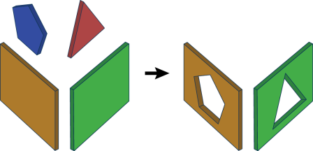
Cuts holes in surface features with other surface features. A surface that is cut by another surface must be co-planar with that second surface, and contain that second surface.
All surfaces are converted into faces (for example, a mesh is converted into faces – one face per mesh part).
Input Ports
Surface features: it is assumed that any two input surfaces within a group either have a strict containment relationship, or are not overlapping.
Output Ports
Contains the output surfaces.
All but one geometrically identical surface will be output through the Unused port. Two surfaces are considered geometrically identical if their geometries match exactly.
Non-geometry properties like coordinate systems, measures, traits, and geometry names are not considered when matching input geometries.
Non-surface features
Parameters
Transformer
Leaving this parameter blank causes the entire set of input surfaces to form a single group. Alternatively, this parameter allows you to select attributes on which to form groups of surface features – each set of features that have the same value for all of these attributes will be processed independently in a group.
No attributes other than Group By attributes will be carried across from the Input features to the output features.
Note: How parallel processing works with FME: see About Parallel Processing for detailed information.
This parameter determines whether or not the transformer should perform the work across parallel processes. If it is enabled, a process will be launched for each group specified by the Group By parameter.
Parallel Processing Levels
For example, on a quad-core machine, minimal parallelism will result in two simultaneous FME processes. Extreme parallelism on an 8-core machine would result in 16 simultaneous processes.
You can experiment with this feature and view the information in the Windows Task Manager and the Workbench Log window.
Yes: This transformer will process input groups in order. Changes on the value of the Group By parameter on the input stream will trigger batch processing on the currently accumulating group. This will improve overall speed if groups are large/complex, but could cause undesired behavior if input groups are not truly ordered.
No: This is the default behavior. Processing will only occur in this transformer once all input is present.
Parameters
This parameter indicates whether or not surface features used to cut other surfaces should be dropped or output.
This parameter will be added to each output feature and will contain "yes" if that feature was used to cut a hole inside some other feature, and "no" if that feature did not cut into any other features.
If a hole list name is specified, the attributes of the features that were used to cut holes in this surface are added to this attribute list.
Note: List attributes are not accessible from the output schema in Workbench unless they are first processed using a transformer that operates on them, such as ListExploder or ListConcatenator. All list attribute transformers are displayed in the Contents pane of the Transformer Help under Lists. Alternatively, AttributeExposer can be used.
If set to Yes, the Normal Tolerance in Degrees and Offset Tolerance parameters are enabled. If set to No, the two parameters are disabled.
Faces must be parallel before they are allowed to cut into each other. If two faces are nearly parallel with normals that are slightly apart, use this parameter to set a tolerance in degrees. The larger the value, the less parallel the faces would have to be while still considered parallel to each other.
Usage Tip: Use this parameter together with Offset Tolerance.
Faces must be co-planar before they are allowed to cut into each other. If two faces are nearly co-planar, but are a small offset from each other, use this parameter to set a tolerance in ground units. The larger the value, the farther away the faces could be while still considered co-planar.
Usage Tip: Use this parameter together with Normal Tolerance in Degrees.
Example
The example below illustrates the input features on the left and the output features on the right. The input consists of surface features that are coplanar. The output consists of features with cut holes wherever the surface features were contained within or intersected other surface features.

Editing Transformer Parameters
Using a set of menu options, transformer parameters can be assigned by referencing other elements in the workspace. More advanced functions, such as an advanced editor and an arithmetic editor, are also available in some transformers. To access a menu of these options, click  beside the applicable parameter. For more information, see Transformer Parameter Menu Options.
Transformer Categories
FME Licensing Level
FME Professional edition and above
Search FME Knowledge Center
Search for samples and information about this transformer on the FME Knowledge Center.