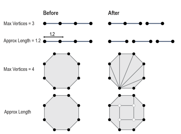
Breaks input features into points, lines, or areas. Chopped features contain the same set of vertices as input features.
This is useful when outputting to a format that has limitations on the number of coordinates in each feature. It can also be used to crudely simplify complex objects.
All new features have the same attributes as the original feature had and are output via the Output port. The optional chopping indicator attribute can be used to distinguish output features which were chopped from output features which were not.
Input Ports
Lines and areas will be processed.
Output Ports
Chopped and untouched features are output to this port.
Parameters
Each Output feature will have up to the specified number of vertices. For example, if an input line consists of 4 vertices, and a Maximum Vertices of 3 is specified, two Output lines would be output: one with 3 vertices and one with 2 vertices.
If this parameter is less than 4, input area features are converted to linear features. If it is set to 1, all input features are broken up into point features.
If the feature is a line and the final piece of the Output line feature does not have the same number of vertices as the other pieces, this attribute (if specified) will be added with a value of “yes”, otherwise this attribute will have the value “no”.
Each Output line feature will be a line feature whose length is close to the value specified in this parameter. Whenever two input vertices may represent the endpoint of an Output line feature, FME chooses the one that results in a length closer to the value of Approximate Length.
For example, if a horizontal line consists of two segments of length 0.8, and you specify 1 for Approximate Length, then the output is expected to be two line features each containing two vertices, and each a length of 0.8.
For area features, the Approximate Length determines the approximate height and width of chopped areas. If vertex spacing along the line is greater than the Approximate Length, larger areas will result. By default, Add Interior Points (Areas Only) is set to Yes, meaning that new vertices may be introduced to the interior of areas.
Yes: New vertices will be introduced while chopping up an input area feature whenever needed. These vertices are guaranteed to fall inside the input area.
No: No new vertices will be introduced. This means if an input area cannot be chopped up without new vertices within the confines of Approximate Length, then it will be output unmodified. It is also possible that many of the pieces produced by chopping will be larger than the Approximate Length, since no smaller pieces can be generated without introducing interior vertices.
This attribute (if specified) will be added with a value of “yes” to any output features which were chopped, and a value of “no” to any output features which were untouched by the transformer.
Usage Notes
Input arcs are stroked prior to chopping. If the chopping operation does not modify a stroked arc, the arc is unstroked and will be output untouched.
Area features are chopped in such a way as to preserve the original area of the feature. That is, the original area feature is cut into smaller areas, which if dissolved together, would match the original area. New vertices may be introduced into the area feature as it is chopped.
Example

Editing Transformer Parameters
Using a set of menu options, transformer parameters can be assigned by referencing other elements in the workspace. More advanced functions, such as an advanced editor and an arithmetic editor, are also available in some transformers. To access a menu of these options, click  beside the applicable parameter. For more information, see Transformer Parameter Menu Options.
Transformer Categories
Search FME Knowledge Center
Search for samples and information about this transformer on the FME Knowledge Center.