Expands or shrinks the boundary segments in the input geometry by a specified amount, and if necessary, connects them using stroked arcs. Aggregate geometries and groups are dissolved after the buffer operation.
Input Ports
Only 2D geometries are accepted as input.
Output
Each point in the output curve will be the specified amount, measured in ground units, away from the input geometry. If the specified buffer amount is too small, a feature with a null geometry is output.
Parameters
If any attributes were specified in this parameter, then all features with the same values for the specified Group By attributes are dissolved together after the buffering operation to create non-overlapping areas.
Note: How parallel processing works with FME: see About Parallel Processing for detailed information.
This parameter determines whether or not the transformer should perform the work across parallel processes. If it is enabled, a process will be launched for each group specified by the Group By parameter.
Parallel Processing Levels
For example, on a quad-core machine, minimal parallelism will result in two simultaneous FME processes. Extreme parallelism on an 8-core machine would result in 16 simultaneous processes.
You can experiment with this feature and view the information in the Windows Task Manager and the Workbench Log window.
No: This is the default behavior. Processing will only occur in this transformer once all input is present.
By Group: This transformer will process input groups in order. Changes on the value of the Group By parameter on the input stream will trigger batch processing on the currently accumulating group. This will improve overall speed if groups are large/complex, but could cause undesired behavior if input groups are not truly ordered.
Each point in the output curve is the specified amount, measured in ground units, away from the input geometry.
To expand an input feature, specify a positive buffer amount.
To shrink an input feature, specify a negative buffer amount.
To leave the input geometry unmodified, specify a buffer amount of 0.
When buffering a line, you can specify the end-cap style.
As the diagrams below illustrate, these caps can be Round (default) or Square, but you can also set this parameter to None.
Round

Square

None

When buffering a line or area, you can specify the corner style.
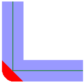
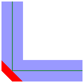
As the diagrams below illustrate, the corner styles can be Round (default), Bevel (chopped), or Miter (pointed). If Miter is used, a limit must be specified using the Miter Limit parameter. If a corner is too pointed for the miter limit, the corner will instead be bevelled.
Round

Bevel

Miter

This parameter controls the smoothness of the stroked arcs in the output buffer boundaries. It specifies what angles should be used to discretize a circular arc. As this parameter decreases in value, the smoothness of the arc connectors increases. This parameter is used for the Round End Cap Style and the Round Corner Style. The value must be between 0 and 90 degrees.
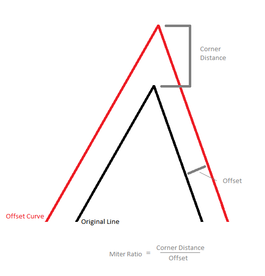
This parameter controls how pointed a buffered corner can be before it is bevelled. It is the highest value that the ratio of corner distance to offset is allowed to have before truncation occurs. A higher number allows for more extreme corner angles.

This parameter specifies the name of a list into which the attributes of the input features are stored. This parameter is useful when using Group By or if input features contain aggregates. Within each group or aggregate, within each dissolved region, attributes from an input feature with the largest area are stored at the head of the list, and no order is defined for the remaining elements.
Note: List attributes are not accessible from the output schema in Workbench unless they are first processed using a transformer that operates on them, such as ListExploder or ListConcatenator. All list attribute transformers are displayed in the Contents pane of the Transformer Help under Lists. Alternatively, AttributeExposer can be used.
Usage Notes
- This transformer creates buffers that are of equal width on either side of a linear input feature. To create offsets to either the left or right-hand side of a feature, use the OffsetCurveGenerator.
FME Knowledge Center
See the FME Knowledge Center for more information on this transformer.
Editing Transformer Parameters
Using a set of menu options, transformer parameters can be assigned by referencing other elements in the workspace. More advanced functions, such as an advanced editor and an arithmetic editor, are also available in some transformers. To access a menu of these options, click  beside the applicable parameter. For more information, see Transformer Parameter Menu Options.
Transformer Categories
Related Transformers
Search FME Knowledge Center
Search for samples and information about this transformer on the FME Knowledge Center.