Creates offset parallel lines on either side of linear features.
Typical Uses
- Creating parallel lines to the left, right, or both sides of a linear feature
How does it work?
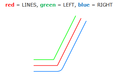
The OffsetCurveGenerator takes in line features and creates new lines on either side of the original. These new lines are placed at a specified Offset distance from the original, on the left and right-hand sides. There is a choice of how corners are created - round, mitered, or beveled.
The new offset lines are output as Right and Left, according to the orientation of the original feature.
In this example, we will create offset lines on either side of a rapid transit line. The original feature is a single line.
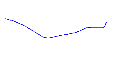
The line is routed into the Lines input port.

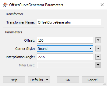
In the parameters dialog, we set the Offset to 100, which will create the new offset lines 100 meters away from the original feature (which is in a UTM projection, ground units in meters). The Corner Style chosen is Round.
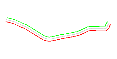
Two new lines are output from the transformer - one on the left side of the original line (shown in green), and one on the right (shown in red).
In a scenario where only one side is needed (left or right), simply disregard the unneeded output port.
Configuration
Input Ports
Offset curves will be built in 2D from linear features. Self intersecting lines are not supported, and may produce unpredictable results. Other types of geometry will be output through the <Rejected> port.
Output Ports
Each point in the output curve will be the specified offset, measured in ground units, away from the input linear geometry. The output ports Left and Right will produce offset curves on either side of the linear geometry.
Features without line geometry are output through this port along with an additional attribute, fme_rejection_code, to indicate the reason for rejection.
Rejected Feature Handling: can be set to either terminate the translation or continue running when it encounters a rejected feature. This setting is available both as a default FME option and as a workspace parameter.
Parameters
| Offset | This parameter, measures in ground units, specifies the distance by which the output curve is offset from the input curve. |
| Corner Style |
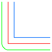
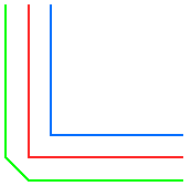
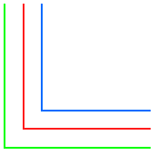
As the diagrams below illustrate, the corner styles of the offset curves can be Round (default), Bevel (chopped), or Miter (pointed). If Miter is used, a limit must be specified using the Miter Limit parameter. If a corner is too pointed for the miter limit, the corner will instead be bevelled. Round
Bevel
Miter
|
| Interpolation Angle |
This parameter, measured in degrees, controls the smoothness of the stroked arcs in the output offset curve. As this parameter decreases in value, the smoothness of the arc connectors increases. The specified value must be between 0 and 90 degrees. |
| Miter Limit |
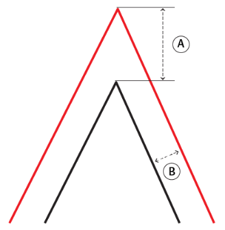
Miter Limit This parameter controls how pointed a buffered corner can be before it is beveled. It is the highest value that the ratio of corner distance to offset is allowed to have before truncation occurs. A higher number allows for more extreme corner angles.
Miter Ratio = Corner distance / Offset
|
Editing Transformer Parameters
Using a set of menu options, transformer parameters can be assigned by referencing other elements in the workspace. More advanced functions, such as an advanced editor and an arithmetic editor, are also available in some transformers. To access a menu of these options, click  beside the applicable parameter. For more information, see Transformer Parameter Menu Options.
Defining Values
There are several ways to define a value for use in a Transformer. The simplest is to simply type in a value or string, which can include functions of various types such as attribute references, math and string functions, and workspace parameters. There are a number of tools and shortcuts that can assist in constructing values, generally available from the drop-down context menu adjacent to the value field.
Using the Text Editor
The Text Editor provides a convenient way to construct text strings (including regular expressions) from various data sources, such as attributes, parameters, and constants, where the result is used directly inside a parameter.
Using the Arithmetic Editor
The Arithmetic Editor provides a convenient way to construct math expressions from various data sources, such as attributes, parameters, and feature functions, where the result is used directly inside a parameter.
Conditional Values
Set values depending on one or more test conditions that either pass or fail.
Parameter Condition Definition Dialog
Content
Expressions and strings can include a number of functions, characters, parameters, and more - whether entered directly in a parameter or constructed using one of the editors.
| These functions manipulate and format strings. | |
| A set of control characters is available in the Text Editor. | |
| Math functions are available in both editors. | |
| These operators are available in the Arithmetic Editor. | |
| These return primarily feature-specific values. | |
| FME and workspace-specific parameters may be used. | |
| Working with User Parameters | Create your own editable parameters. |
Reference
|
Processing Behavior |
|
|
Feature Holding |
No |
| Dependencies | |
| FME Licensing Level | FME Base Edition and above |
| Aliases | BufferCurveGenerator |
| History | |
| Categories |
FME Knowledge Center
The FME Knowledge Center is the place for demos, how-tos, articles, FAQs, and more. Get answers to your questions, learn from other users, and suggest, vote, and comment on new features.
Search for all results about the OffsetCurveGenerator on the FME Knowledge Center.
Examples may contain information licensed under the Open Government Licence – Vancouver
