Detects selected issues in input features, and optionally repairs detected issues. Each input feature is processed individually.
The GeometryValidator is a very powerful transformer, suitable for advanced users. The help topic consists of a number of reference sections:
Output Dependencies for Issues, Assuming Input Dependencies Respected
Input Ports
All input geometries are accepted but not all of them are subject to issue detection. Some geometries are only superficially supported (for example, point and lines will always pass detection on surface and solid issues).
Some geometries are not currently supported. If a feature consists solely of currently unsupported geometries, it will be output onto the Passed port. If a feature contains a geometry that is not currently supported, a once-per-session warning message will be printed in the log.
Note: If you discover a Passed feature that is clearly invalid, check the log first to see whether that feature might contain a geometry that is not currently supported.
Output Ports
When a feature is output through the Passed port, it has passed issue detection.
If a feature is output through the Failed port, it has failed issue detection. Features are output from this port for three reasons:
- When Attempt Repair is set to No, this port contains features in which selected issues are detected.
- When Attempt Repair is set to Yes, this port contains features that could not be fully repaired. Whether a feature is fully repaired can be determined by observing the repair state attribute associated with reported issues. If any detected issue is reported as Not Fully Repaired, then the feature will, as a whole, be considered not fully repaired, and is output via the Failed port.
- When Attempt Repair is set to Yes, this port can contain Remnant features. For example, repairing a self-intersecting donut could produce a repaired area and a number of remnant areas from holes that extend beyond the outer shell.
To distinguish between the above situations, ensure that you specify a Detected Issue List Name.
This port is used only when Attempt Repair is set to Yes. If a feature is output onto the Repaired port, at least one issue has been detected, and all detected issues have been repaired.
This port outputs point locations that correspond to the issues found by the Failed and Repaired ports. Each location will have attributes explaining what issue it corresponds to, as well as the attributes of the original feature.
This port outputs the smallest part(s) of the geometry that show the issues found by the Failed and Repaired ports. Each part will have attributes explaining what issue it corresponds to, as well as the attributes of the original feature.
Parameters
Note: To fully understand the choices and information in these parameters, please refer to other sections of this help topic.
Use this parameter to quickly select multiple related issues. When you select an issues set, the related issues are selected in the issues table. Alternatively, to select your own issues in the table, specify Custom. For more information about detection and repair of issues, see Issues below, and GeometryValidator Issues Table.
| Table Column Name | Description |
|---|---|
| Issue | Select the issues to detect or repair. For more information, see Issues below, and GeometryValidator Issues Table. |
| Parameters | Specify parameters specific to each selected issue. |
| Repairable | Describes whether or not a selected issue can be repaired. |
Selected issues are detected in the order shown in the Issue column. Issue detection ordering can be changed by highlighting an issue and then clicking the small up/down arrows just outside the issues table.
For more information about the issues that are detected and/or repaired, see GeometryValidator Issues Table.
Issue detection only occurs within geometries, including geometric properties such as text rotation and arc sweep angle. That means attributes, traits, geometry names, and other non-geometric properties are not processed.
Features with a geometry unsuited to a test (like line features in a test for area orientation) count as a pass and no repair is attempted.
In general, input geometry types are preserved unless they cannot be.
For example, an arc that degenerates into a point cannot remain an arc and at the same time be non-degenerate. So, when the issue Degenerate and Corrupt Geometries is selected, and Attempt Repair is set to Yes, the arc should be repaired into a point.
As another example, a donut that contains a non-degenerate outer shell, a degenerate hole, and a non-degenerate hole can remain a donut after degeneracy repair. The donut simply drops the degenerate hole, and remains a donut.
If an input geometry contains multiple issues, but only a subset of them is being detected and repaired, expect undefined behavior. For example, if an arc containing a NaN (Not a Number) is being repaired only for degeneracy and corruption, the number of NaNs in that arc could increase. As another example, if you attempt to repair self-intersections in a degenerate geometry, it may come out with a different geometry type and lose its coordinates.
The detection and repair of the following issues depends on the absence of other issues:
| Degenerate or Corrupt Geometries | no NaNs or infinities in input |
|
Tip: To avoid undefined behavior, select Degenerate or Corrupt Geometries and Contains NaN (Not a Number) or Infinity before selecting Self-Intersections in 2D. |
no NaNs, infinities, degeneracies, or corruptions in input |
| Non-Planar Surfaces | no NaNs or infinities in input |
| Invalid Solid Boundaries or Invalid Solid Voids | no NaNs or infinities, duplicate consecutive coordinates, degeneracies or corruptions, or self-intersections within individual faces in input |
| Invalid Solid Voids | no invalid solid boundaries |
Output Dependencies for Issues, Assuming Input Dependencies Respected
Repairing the following issues can produce other issues:
| Contains NaN (Not a Number), Infinity, or -0 | can produce degenerate output |
| Degenerate or Corrupt Geometries | can produce self-intersecting output |
| Contains Null Geometry Parts | can produce degenerate output |
| Duplicate Consecutive Points | can produce degenerate output |
| Self-Intersections in 2D | can produce degenerate output |
| Invalid Solid Boundaries | can produce degenerate faces in the boundary |
The recommended ordering of issues to detect is built into the Issue column. If a different ordering is desired, highlight an issue, then click the up and down arrows on the right side of the issues table.
Tip: Different orderings of issues to detect and repair may cause output geometries to change.
If Process Measure is selected, the following operations will also account for measures. Don’t Process Measure is the default.
If Attempt Repair is set to No, NaNs and infinities will be detected.
If Attempt Repair is set to Yes, one of two operations will take place:
- If there is redundant information, such as in the case of arcs with end points, the redundant information will be used to compute replacement values for NaNs.
- If there is no redundant information, NaNs will be removed, which could trigger the removal of a coordinate or the conversion of the geometry to IFMENull.
For example, when Attempt Repair is set to Yes, an arc containing a NaN rotation will be replaced with an IFMENull because there is no redundant information to recalculate the rotation. As another example, an arc that has NaNs in the end points can have its end points recalculated based on the center point and the arc properties.
If Attempt Repair is set to No, IFMENull parts will be detected. Note that an IFMENull by itself is not considered a “part”. Only IFMENulls that are the children of some aggregate will be considered “parts”.
If Attempt Repair is set to Yes, IFMENull parts will be removed.
If Attempt Repair is set to No, consecutive duplicate points are detected.
If Attempt Repair is set to Yes, consecutive duplicate points are removed.
If Check Z Values is set to No, duplicate detection is performed in 2D.
If Check Z Values is set to Yes, duplicate detection is performed in 3D.
Parameters
When viewed in 2D (ignoring Z), a path (which may define the border of a polygon) may appear to be closed as shown in the left figure below. This same path, when viewed in 3D, may appear to be open as shown in the right figure below.
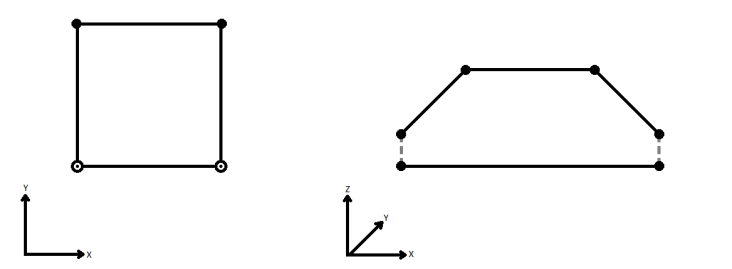
To specify how (and if) paths should be closed in 3D, select one of the listed modes.
| Mode | Description | Example |
|---|---|---|
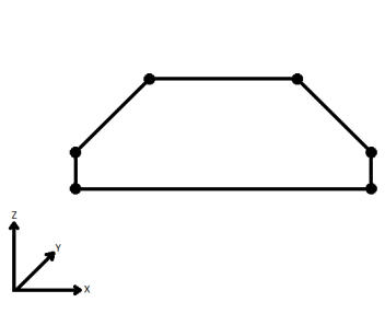
| Extend | The Curve is extended so that all vertices are left at their original location. |
|
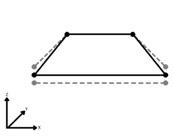
| Average | Subsequent vertices that are not connected, but share an x and a y value are combined into one vertex, whose Z value is the average of the original two. |
|
| First Wins | Subsequent vertices that are not connected, but share an x and a y value are combined into one vertex, whose Z value is taken from the first encountered vertex. |
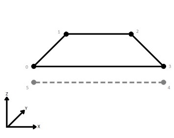
|
| Last Wins | Subsequent vertices that are not connected, but share an x and a y value are combined into one vertex, whose Z value is taken from the last encountered vertex. |
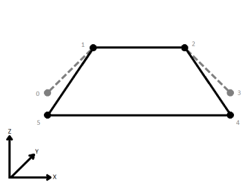
|
| Ignore | Z values are ignored. No change is made to the way the nodes are connected. |
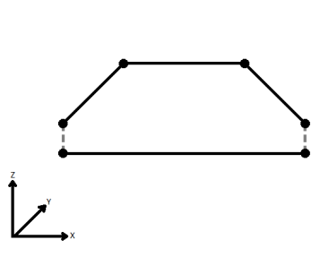
|
If set to Auto, a tolerance value will be automatically calculated for each geometry part, based on the properties of the geometry part. If set to Custom, the user may specify an attribute or a fixed value for the tolerance.
The Tolerance parameter describes the maximum difference, in ground units, permitted between the explicit and implicit end points of an arc. If the difference exceeds this tolerance, an arc is flagged as corrupt. If the difference exceeds the tolerance but is as accurate as possible within the limits of numerical precision, an arc will not be considered corrupt.
If Attempt Repair is set to No, degeneracies and corruptions will be detected. A degenerate geometry is one whose geometry type can be simplified. For example, a polygon that has 0 area is degenerate, and can be simplified to a line, point, or IFMENull. A corrupt geometry in contrast contains conflicts in the geometry definition, such as an arc whose angles and endpoints disagree.
If Attempt Repair is set to Yes, degeneracies and corruptions are repaired in combination. It would not be helpful to separate this issue into two. If a degenerate geometry is repaired into a corrupt geometry, or vice versa, the output could be in worse shape than the input.
As an example, a donut that contains a degenerate hole will become corrupt after the degenerate hole is repaired into a point in place. If you do not repair this point-hole corruption in the donut definition, the result would be a donut that is “sicker” than the input. The correct action is to remove the point-hole from the donut.
In the case of meshes, parts containing invalid indices will be detected. In the case of corrupt vertex normal or texture coordinate indices, only that information will removed from the corrupt part upon repair. If the vertex indices are corrupt, the invalid part will be deleted from the repaired mesh.
As a second example, a corrupt arc whose angles and endpoints mismatch may be repaired into a degenerate arc that is equivalent to a point. If you stopped there and output the degenerate arc, you could end up with more downstream issues than not repairing the arc at all. The correct action is to convert the arc into a point.
Expect that arcs with 0 curvature will be replaced by, or stroked into, a line or point. Arcs with endpoints may be subject to precision limitations that cause a drift between the explicit endpoints, and the implicit arc definition. The parameters below may be used to control the amount of endpoint drift that is tolerated before an arc is flagged as corrupt.
Parameters
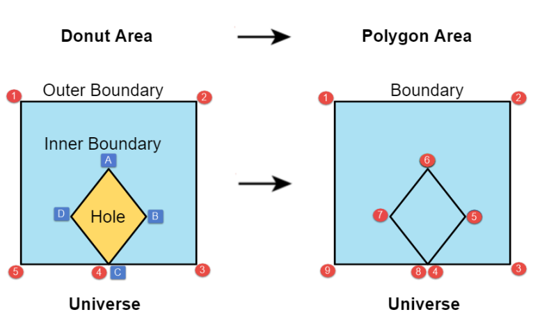
If set to Yes and if Attempt Repair is set to Yes, then donuts that have a hole touching the outer boundary will have the hole added to the outer boundary. This will convert the outer boundary to a pinch polygon. This option will only affect donut holes touching the original outer boundary. The donuts that have been repaired may become donuts without holes, and thus become degenerate.
Example
| The example diagram below illustrates a donut with a hole touching its outer boundary on the left (Donut Area). The hole is added to the outer boundary of the donut as shown on the right (Polygon Area). The donut nodes are shown in the red numbered sequence while the hole is shown in the blue alphabetical sequence. |
|
|
When viewed in 2D (ignoring Z), a path (which may define the border of a polygon) may appear to be closed as shown in the left figure below. This same path, when viewed in 3D, may appear to be open as shown in the right figure below.

If using the “Repair” mode, this parameter specifies how ambiguous Z values for self-intersection locations are chosen. Ambiguous Z values occur when two line segments share an X and Y value, but have a differing Z value.
| Mode | Description | Example |
|---|---|---|
| Extend | The Curve is extended so that all vertices are left at their original location. |

|
| Average | Subsequent vertices that are not connected, but share an x and a y value are combined into one vertex, whose Z value is the average of the original two. |

|
| First Wins | Subsequent vertices that are not connected, but share an x and a y value are combined into one vertex, whose Z value is taken from the first encountered vertex. |

|
| Last Wins | Subsequent vertices that are not connected, but share an x and a y value are combined into one vertex, whose Z value is taken from the last encountered vertex. |

|
| Ignore | Z values are ignored. No change is made to the way the nodes are connected. |

|
If Attempt Repair is set to No, self-intersection points are detected.
If Attempt Repair is set to Yes, an input geometry with self-intersections will be divided into a collection of geometry parts that do not contain self-intersections. For example, a figure-8 polygon that has a “waist size” of 0 will be repaired into an IFMEMultiArea of two polygons. As another example, meshes, triangle strips and triangle fans will be repaired into composite surfaces.
Expect self-intersections to be detected in x and y only.
Duplicate coordinates (duplicate in x and y) are considered self-intersections and are reported as such. Duplicate consecutive coordinates are reported as a single self-intersection point.
Faces are rotated onto the x-y plane, self-intersected in x and y, and then un-rotated.
Aggregates, composite surfaces, meshes, triangle strips, and triangle fans are tested for self-intersection on a per-part (or per-face) basis, but the parts are not self-intersected against each other. Donut holes and rings are self-intersected against each other. For example, if a composite surface has a face that self-intersects, it will be output via the Failed or Repaired port. If a composite surface has two faces that intersect each other but do not self-intersect on their own, the composite surface will be output via the Passed port.
Self-intersections are reported via .location traits. When self-intersections are detected, but no self-intersection points are available for reporting, the transformer reports a nearby location.
If Attempt Repair is set to No, non-planar faces and surface parts, such as mesh parts or parts of a composite surface, will be detected. A non-planar face or surface part does not have all of its vertices on the same plane in 3D space.
If Attempt Repair is set to Yes, non-planar faces and surface parts will be triangulated.
Also Check Areas
If set to No, this check will output all areas through the Passed port. If set to Yes, this check will determine an area’s output port based on its planarity.
Thickness Mode
If set to Automatic, thickness values will be automatically calculated for each geometry part. If set to Custom, the user may specify an attribute or a fixed value for the thickness. If set to Ignore, the thickness check will be ignored.
Thickness
The Thickness parameter describes the maximum “thickness” a face can have before it is considered non-planar. See FaceReplacer.
Angular Mode
If set to Automatic, surface normal deviation values will be automatically calculated for each geometry part. If set to Custom, the user may specify an attribute or a fixed value for the surface normal deviation. If set to Ignore, the surface normal deviation check will be ignored.
Surface Normal Deviation (degrees)
The Surface Normal Deviation parameter describes the maximum deviation between the average surface normal of a face and the surface normals resulting from a triangulation of that face, before it is considered non-planer. See FaceReplacer.
The following family of issues can be detected:
- Vertices Not Used
- Not Enough Faces
- Face Wrong Orientation
- Not a Valid 2-Manifold
- Surface Self Intersects
- Surface Not Closed
- Surface Wrong Orientation
- Multiple Connected Components
If no issues are detected, a solid geometry will be output via the Passed port. Informally, a Passed solid boundary is water-tight, non-self-intersecting and properly oriented.
If Attempt Repair is set to No, the above family of issues will be detected within solid geometries.
If Attempt Repair is set to Yes, solid geometries with open boundaries, too few faces, reversed orientation, or multiple components will be repaired. All input solids will first be triangulated. Open solid boundaries and boundaries with too few faces will be repaired by filling the disconnected regions in the boundary with triangles. Incorrect orientations will be fixed by reversing the surface normal of all faces that compose the solid. If Flip Appearances is selected, the appearances of each face will also switch sides, otherwise appearances will not move. A boundary with multiple connected components will be repaired by removing all components except the one with the most faces.
A void is a cavity, or an empty region within a solid, and is defined by an inner boundary. A solid is defined by an outer boundary and a number of inner boundaries.
The following family of issues can be detected:
- Duplicate Shells
- Shells Intersect
- Inner Shell Outside Outer
- Interior of Shell Not Connected
- Invalid Solid Boundaries
If no issues are detected, the solid geometry will be output via the Passed port. Informally, a Passed solid is a solid with inner boundaries that reside completely within the outer boundary and none of the boundaries intersect each other.
Tip: Self-intersections in boundaries are not detected. To detect and repair self-intersections in the boundaries, select Invalid Solid Boundaries.
If Attempt Repair is set to No, the above family of issues will be detected within solid geometries.
If Attempt Repair is set to Yes, a solid geometry with these issues will be repaired by subtracting the voids from the outer boundary. If the repaired solid is the empty set, the original solid will be output onto the Failed port and gain a .repair_state of Not Fully Repaired.
The input geometry will be evaluated according to OGC standards.
See http://www.opengeospatial.org/standards/sfa for more information.
For OGC Valid checks, the OGC Version parameter specifies which version of the standard to use.
If a geometry is determined to be OGC simple/valid, it will be output via the Passed port. Otherwise it will be output via the Failed port.
Note: When Fails OGC Simple or Fails OGC Valid is enabled, aggregate geometries are treated as OGC GeometryCollections, and multis are treated as OGC Multis.
If Attempt Repair is set to No, geometries containing a mixture of 2D and 3D parts will be detected.
If Attempt Repair is set to Yes, one of two operations will take place:
- If Force Dimension is set to 2D, all geometry parts that are 3D will be forced to 2D.
- If Force Dimension is set to 3D, all geometry parts that are 2D will be forced to 3D and their z value will be set to the Default Z Value.
Some geometries, such as meshes and faces, support appearances. These geometries may form part of complex surfaces and solids. In some cases, these appearances may have raster-based textures associated with them. If this is the case, then it is also necessary for the corresponding geometries to have texture coordinates. Without texture coordinates, there is not enough information on how to render the texture on the geometry when visualizing it, for example.
Missing texture coordinates are detected and reported in bulk. That is, regardless of the number of vertices with missing texture coordinates, only one such vertex is reported per geometry.
If Attempt Repair is set to No, missing texture coordinates are detected.
If Attempt Repair is set to Yes, every geometry that has at least one missing texture coordinate will have all of its texture coordinates re-computed. Geometries with no missing texture coordinates are left unmodified. For example, if a solid has 6 faces, one of which is missing texture coordinates, then 5 of the 6 faces will not be modified, and 1 of the 6 will have its texture coordinates re-computed. When computing missing texture coordinates, the entire texture is draped onto the geometry, and the texture is draped in the direction of the surface normal of the geometry.
Vertices without normals are detected and reported in bulk. That is, regardless of the number of vertices with missing normals, only one such vertex is reported per geometry.
If Attempt Repair is set to No, missing vertex normals are detected.
If Attempt Repair is set to Yes, every geometry that has at least one normal missing will have all its normals re-computed. Each computed vertex normal is equivalent to the normal of the face that the vertex belongs to. For meshes, newly computed normals will be stored inside their normal pools. For other surfaces, the measures named fme_vertex_normal_x, fme_vertex_normal_y, and fme_vertex_normal_z, will be used to store the vertex normals. Rectangle faces will be repaired into faces. Triangle strips and triangle fans will be repaired into composite faces.
Areas, such as polygons, ellipses, and donuts, have an orientation. Their orientation can be either left-handed, right-handed or invalid. A left-handed orientation means the area's outer boundary has its vertices arranged in a counterclockwise direction, and the holes have their vertices in a clockwise direction. In a right-handed orientation, the area's outer boundary has its vertices arranged in a clockwise direction, and the holes have their vertices in a counterclockwise direction. An example of an invalid area, would be a donut, whose inner and outer rings are all right-handed, or all left-handed.
If Attempt Repair is set to No, then the orientation of all areas will be checked. Selecting Left for the mode will check if all areas follow the left-hand rule. Selecting Right for the mode will check if all areas follow the right-hand rule. Selecting Valid will check that each area is either left handed, or right handed.
This check will not produce meaningful results for degenerate features whose orientation is ambiguous, such as a figure-8 boundary, or a polygon with no coordinates.
If Attempt Repair is set to Yes, all areas will be forced to the specified mode.
Output
Detected issues will be reported within Attribute lists and Trait lists. These lists will have the same name, which is the value of this parameter. If this list name is left empty, no detected issues will be reported.
Issue locations are all reported as local coordinates, as opposed to world coordinates.
Issue attributes and traits do not accumulate through multiple GeometryValidators. In fact, the first operation GeometryValidator performs is to remove existing issue attributes and traits that collide with the specified Detected Issue List Name. This removal takes place even if no issues are selected.
Note: List attributes are not accessible from the output schema in Workbench unless they are first processed using a transformer that operates on them, such as ListExploder or ListConcatenator. All list attribute transformers are displayed in the Contents pane of the Transformer Help under Lists. Alternatively, AttributeExposer can be used.
Note: To preserve existing issue attributes and traits reported by an upstream GeometryValidator, modify Detected Issue List Name.
If this parameter is set to Yes, detected issues will either be fully repaired, in which case the feature would be output to the Repaired port, or not fully repaired, in which case the feature would gain at least one .repair_state of Not Fully Repaired and be output to the Failed port.
If a single issue is selected for repair, it can be expected that the primary (as opposed to remnant) output feature will either have all occurrences of the selected issue repaired, or gain a .repair_state of Not Fully Repaired. For example, if Self-Intersection in 2D is selected with Attempt Repair set to Yes, the primary output feature can be expected to be free of self-intersections.
If this parameter is set to No, detected issues will not be repaired, and features with detected issues will be output via the Failed port.
Note: You can preview issue repair by setting Attempt Repair to No. However, this preview will only align with the actual repair if you select exactly one issue to detect, or if you select a set of independent issues.
When Attempt Repair is set to Yes, it is possible for a geometry part to become incompatible with its container geometry after repair. In some cases, these geometry parts are removed or output as remnants. In other cases, these geometry parts are kept, and their container geometries change geometry types, so that the parts and the container become compatible again.
Here is a list of container geometries whose incompatible parts are removed or output as remnants:
- IFMEDonut
- IFMEBRepSolid
- IFMEPath
- IFMEMesh
- IFMECompositeSurface
- IFMECompositeSolid
Here is a list of container geometries that will change types to accommodate its incompatible parts:
- IFMEMultiArea
- IFMEMultiCurve
- IFMEMultiPoint
- IFMEMultiSurface
- IFMEMultiSolid
- IFMEMultiText
- IFMETriangleStrip
- IFMETriangleFan
- IFMEMesh
There is an exception to the first list of container geometries when Degenerate or Corrupt Geometries is selected and Attempt Repair is set to Yes. In such cases, if a container geometry becomes empty after all degeneracies and corruptions have been removed, then one of the incompatibly repaired parts will be output as the Repaired feature.
See FME Geometry Model for more information on geometry types.
If the Summary Mode is set to Detailed then information will be reported at the Trait Level and the Attribute Level.
At the Trait level, six pieces of information are reported:
| Information | Required/Optional | Description |
|---|---|---|
| .count | Required | Reports the number of occurrences of the issue. |
| .issue_found | Required | Reports the issue detected. |
| .repair_state | Optional |
Distinguishes between Remnant and Not Fully Repaired features and geometries. If a feature or geometry passes issue detection or becomes fully repaired, then this attribute or trait is not set, as setting it in these cases would provide duplicate information that unnecessarily clutters reporting. |
| .location_sample | Optional | Reports a location where the issue was detected. |
| .supplementary_info | Optional | Reports additional information about the issue. |
| .supplementary_info{0..n} | Required |
Reports extra information on specific occurrences of the issue. It can report three pieces of information: .count (optional): reports the number of incidents within a specific occurrence of the issue. For example, this could be used to report the number of duplicated points at a specific location. .details (required): reports the issue subcase for a specific occurrence. If there are no subcases for an issue, this value will default to Miscellaneous. .location (optional): reports the location of a specific occurrence of the issue. |
Attribute Level
At the Attribute level, five pieces of information are reported:
| Information | Required/Optional | Description |
|---|---|---|
| .count | Required | Reports the total number of occurrences of the issue across all parts of the geometry. |
| .issue_found | Required | Reports the issue detected. |
| .repair_state | Optional |
Distinguishes between Remnant and Not Fully Repaired features and geometries. If a feature or geometry passes issue detection or becomes fully repaired, then this attribute or trait is not set, as setting it in these cases would provide duplicate information that unnecessarily clutters reporting. |
| .location_sample | Optional | Reports a location where the issue was detected. |
| .supplementary_info{0..n} | Required |
Reports information on unique subcases of the issue. It can report three pieces of information: .count (required) Reports the total number of occurrences of the supplementary_info across the geometry. .details (required): Reports the issue subcase for a specific occurrence. If there are no subcases for an issue, this value will default to Miscellaneous. .location_sample (optional): Reports a location where the supplementary_info was detected. |
The Attribute level list is intended as a summary of the Trait level lists. Since degenerate geometries may be removed upon repair, the Attribute level list may sometimes have more information in it than what is present on the Traits of the final geometries.
If the Summary Mode is set to Brief, nothing will be reported at the Trait level, and no supplementary_info will be reported at the Attribute level.
If the Summary Mode is set to None, nothing will be reported.
Editing Transformer Parameters
Using a set of menu options, transformer parameters can be assigned by referencing other elements in the workspace. More advanced functions, such as an advanced editor and an arithmetic editor, are also available in some transformers. To access a menu of these options, click  beside the applicable parameter. For more information, see Transformer Parameter Menu Options.
Transformer Categories
FME Licensing Level
FME Desktop edition and above
Search FME Knowledge Center
Search for samples and information about this transformer on the FME Knowledge Center.
Tags Keywords: GeometryRepairer GeometryCleaner Mender Fixer NaNRemover InfinityRemover NullRemover IFMENullRemover GeometryTypeRepairer DegenerateGeometryRepairer CorruptGeometryRepairer MeshNormalRepairer FeatureValidator FeatureRepairer FeatureCleaner GeometryOGCValidator DuplicateCoordinateRemover SelfIntersector OGC-simple OGC-valid Duplicated Corrupted self intersected damaged erroneous error data repair fix bad data
