Repairs area topologies by resolving gaps and overlaps between adjacent areas. An overlap occurs where two or more areas intersect each other, creating an region covered by multiple areas. A gap occurs where two or more areas fail to meet at a boundary.
How does it work?
The AreaGapAndOverlapCleaner forms a 2D planar partition from the input areas and assigns each gap and overlap to one of the adjacent areas.
Usage Notes
- Requires valid area geometries. For example, self-intersecting, or degenerate areas will not be properly repaired.
- Donut holes, if not filled by another area, are gaps in the 2D planar partition.
- The AreaGapAndOverlapCleaner resolves gaps and overlaps between adjacent areas. If a single area is input, it will be output unchanged.
- The AreaGapAndOverlapCleaner may create spikes when merging gaps to adjacent areas. However, spikes smaller than the tolerance will never be created. If these spikes are not desired, try increasing the tolerance.
Configuration
Input Ports
Only area geometries are accepted as input.
Output Ports
Features that have been cleaned are output via this port.
Geometries that collapsed within tolerance will be output via the Remnants port. Additionally, features that did not have any geometry left after overlap resolution will also be output via this port with null geometries.
Features with invalid geometries will be rejected and output via this port. Additionally, if the Repair Method parameter is Priority (Edge Preserving) or Priority (Area Enlarging), features with invalid priority attributes will also be rejected via this port.
Rejected features will have an fme_rejection_code attribute with one of the following values:
INVALID_GEOMETRY_TYPE
INVALID_PARAMETER_PRIORITY_ATTRIBUTE
Rejected Feature Handling: can be set to either terminate the translation or continue running when it encounters a rejected feature. This setting is available both as a default FME option and as a workspace parameter.
Parameters
| Group By | The default behavior is to use the entire set of features as the group. This option allows you to select attributes that define which groups to form. |
| Tolerance |
The minimum distance between geometries in 2D before they are considered equal, in ground units, during construction of the 2D planar partition. If the tolerance is Automatic, a tolerance will be automatically computed based on the location of the input geometries. Additionally, a custom tolerance may be used. |
| Fill All Gaps |
Yes: All gaps in the 2D planar partition will be filled. No: Only gaps within the tolerance will be filled. |
| Repair Method |
Specifies how to resolve gaps and overlaps once the planar partition has been created. Longest Boundary: The polygon with the longest border length to the conflict will be chosen. Random: The polygon to merge a conflicting region into will be selected at random. Priority (Edge Preserving): Allows control of the priority of individual polygons in the repair process. The boundary of the higher priority polygon is preserved in this mode. Gaps between polygons will be assigned to the lower priority neighboring polygon, and overlaps will be assigned to the higher priority neighboring polygon. This method is used in conjunction with the Priority Attribute parameter. Priority (Area Enlarging): Allows control of the priority of individual polygons in the repair process. The area of the higher priority polygon will be enlarged in this mode. Gaps and overlaps between polygons will be assigned to the higher priority neighboring polygon. This method is used in conjunction with the Priority Attribute parameter. |
| Priority Attribute |
The Priority Attribute should be a non-negative integer value, with 0 meaning highest priority. It is enabled when the Repair Method parameter is Priority (Edge Preserving) or Priority (Area Enlarging). |
| Aggregate Handling |
Choose how aggregate geometries are to be handled. Deaggregate: Decompose aggregates into their individual components. With this setting, the transformer might output more features than were given as inputs. Reject: Do not process aggregates and output them via the <Rejected> port. |
| Connect Z Mode |
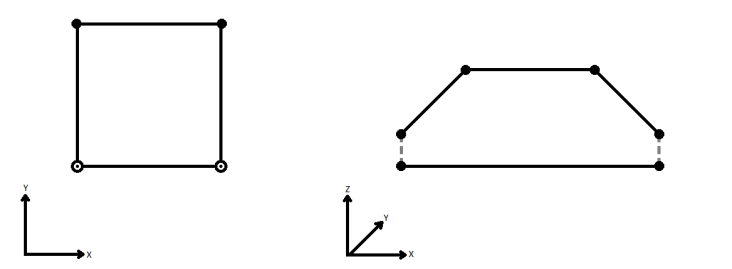
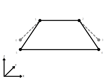
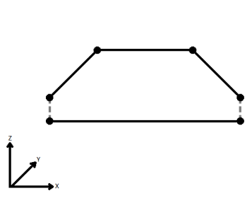
If applicable, select a method for handling z values. When viewed in 2D (ignoring Z), a path (which may define the border of a polygon) may appear to be closed as shown in the left figure below. This same path, when viewed in 3D, may appear to be open as shown in the right figure below.
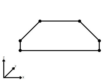
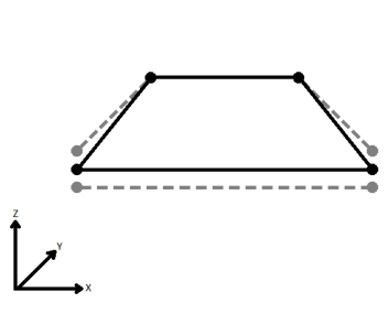
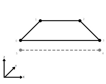
To specify how (and if) paths should be closed in 3D, select one of the listed modes.
|
||||||||||||||||||
| Measures/Z Conflict Value |
This parameter specifies how to deal with geometries that have a measure, but are missing at least one value, or that have z values, but are missing at least one value. None (Drop Values): Remove incomplete measures or z values. Compute: Look at the values on either side of the missing value, and compute an estimate. Custom Value: The missing values are filled in with the specified custom default value. |
||||||||||||||||||
| Treat Measures as | When using the Compute mode to compute missing measure values, measures can be considered Continuous, and linearly interpolated from their neighbors, or they can be Discrete, and taken exactly from the nearest neighbor. |
Editing Transformer Parameters
Using a set of menu options, transformer parameters can be assigned by referencing other elements in the workspace. More advanced functions, such as an advanced editor and an arithmetic editor, are also available in some transformers. To access a menu of these options, click  beside the applicable parameter. For more information, see Transformer Parameter Menu Options.
Defining Values
There are several ways to define a value for use in a Transformer. The simplest is to simply type in a value or string, which can include functions of various types such as attribute references, math and string functions, and workspace parameters. There are a number of tools and shortcuts that can assist in constructing values, generally available from the drop-down context menu adjacent to the value field.
Using the Text Editor
The Text Editor provides a convenient way to construct text strings (including regular expressions) from various data sources, such as attributes, parameters, and constants, where the result is used directly inside a parameter.
Using the Arithmetic Editor
The Arithmetic Editor provides a convenient way to construct math expressions from various data sources, such as attributes, parameters, and feature functions, where the result is used directly inside a parameter.
Conditional Values
Set values depending on one or more test conditions that either pass or fail.
Parameter Condition Definition Dialog
Content
Expressions and strings can include a number of functions, characters, parameters, and more - whether entered directly in a parameter or constructed using one of the editors.
| These functions manipulate and format strings. | |
| A set of control characters is available in the Text Editor. | |
| Math functions are available in both editors. | |
| These operators are available in the Arithmetic Editor. | |
| These return primarily feature-specific values. | |
| FME and workspace-specific parameters may be used. | |
| Working with User Parameters | Create your own editable parameters. |
Reference
|
Processing Behavior |
|
|
Feature Holding |
Yes |
| Dependencies | |
| FME Licensing Level | FME Professional Edition and above |
| Aliases | SliverRemover |
| History | |
| Categories |
FME Knowledge Center
The FME Knowledge Center is the place for demos, how-tos, articles, FAQs, and more. Get answers to your questions, learn from other users, and suggest, vote, and comment on new features.
Search for all results about the AreaGapAndOverlapCleaner on the FME Knowledge Center.
Examples may contain information licensed under the Open Government Licence – Vancouver
