LineCombiner
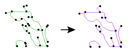
Takes lines and connects them to form longer lines. Each connecting line must meet at the exact same start/end point, but otherwise they must not intersect.
Any nodes with only two lines connecting to them (sometimes called pseudonodes) are removed. Lines remain broken at points where three or more converge.
Note: Duplicate lines passed into the transformer will be consumed by the transformer.
Output Ports
All linear features produced by this transformer are sent to the Line port.
Parameters
Transformer
The Group By list of attributes separates the input data into sets which are considered independently when the node removal is done. Only attributes that are listed in the Group By list will be passed to subsequent transformers – all other attributes are removed.
Note: How parallel processing works with FME: see About Parallel Processing for detailed information.
This parameter determines whether or not the transformer should perform the work across parallel processes. If it is enabled, a process will be launched for each group specified by the Group By parameter.
Parallel Processing Levels
For example, on a quad-core machine, minimal parallelism will result in two simultaneous FME processes. Extreme parallelism on an 8-core machine would result in 16 simultaneous processes.
You can experiment with this feature and view the information in the Windows Task Manager and the Workbench Log window.
No: This is the default behavior. Processing will only occur in this transformer once all input is present.
By Group: This transformer will process input groups in order. Changes of the value of the Group By parameter on the input stream will trigger batch processing on the currently accumulating group. This will improve overall speed if groups are large/complex, but could cause undesired behavior if input groups are not truly ordered.
Using Ordered input can provide performance gains in some scenarios, however, it is not always preferable, or even possible. Consider the following when using it, with both one- and two-input transformers.
Single Datasets/Feature Types: Are generally the optimal candidates for Ordered processing. If you know that the dataset is correctly ordered by the Group By attribute, using Input is Ordered By can improve performance, depending on the size and complexity of the data.
If the input is coming from a database, using ORDER BY in a SQL statement to have the database pre-order the data can be an extremely effective way to improve performance. Consider using a Database Readers with a SQL statement, or the SQLCreator transformer.
Multiple Datasets/Feature Types: Since all features matching a Group By value need to arrive before any features (of any feature type or dataset) belonging to the next group, using Ordering with multiple feature types is more complicated than processing a single feature type.
Multiple feature types and features from multiple datasets will not generally naturally occur in the correct order.
One approach is to send all features through a Sorter, sorting on the expected Group By attribute. The Sorter is a feature-holding transformer, collecting all input features, performing the sort, and then releasing them all. They can then be sent through an appropriate filter (TestFilter, AttributeFilter, GeometryFilter, or others), which are not feature-holding, and will release the features one at a time to the transformer using Input is Ordered By, now in the expected order.
The processing overhead of sorting and filtering may negate the performance gains you will get from using Input is Ordered By. In this case, using Group By without using Input is Ordered By may be the equivalent and simpler approach.
In all cases when using Input is Ordered By, if you are not sure that the incoming features are properly ordered, they should be sorted (if a single feature type), or sorted and then filtered (for more than one feature or geometry type).
As with many scenarios, testing different approaches in your workspace with your data is the only definitive way to identify performance gains.
Parameters
Input lines with different values for these attributes will not be combined.
If this parameter is set to Yes, two lines with the same values for the attributes selected above will not be combined if the node at which they meet is also connected to another line with different values for these attributes.
Input Feature Topology indicates the type of vertices the input features contain:
- End noded means only the start and end points will be considered for combining lines, and other vertices will be ignored.
- Vertex noded means all vertices will be considered when combining lines.
Attribute Accumulation
Specifies how attributes should be accumulated. If Drop Incoming Attributes is selected, all incoming attributes are removed from the features. Merge Incoming Attributes merges all attributes from overlapping features. Use Attributes From One Feature takes all attributes from one representative feature.
Allows you to specify a List Name.
If a List Name is supplied, for each output feature, a list is created of all the attributes of input features that contain the output feature. A list with the same name is created for traits.
Note: List attributes are not accessible from the output schema in Workbench unless they are first processed using a transformer that operates on them, such as ListExploder or ListConcatenator. All list attribute transformers are displayed in the Contents pane of the Transformer Help under Lists. Alternatively, AttributeExposer can be used.
All Attributes: Every attribute from all input features that created an output surface will be added to the list specified in List Name.
Selected Attributes: Only the attributes specified in the Selected Attributes parameter will be added to the list specified in List Name.
The attributes to be added to the list when Add To List is Selected Attributes.
An optional attribute to include in the generated list, which indicates whether the direction of that input feature has been preserved (using same) or reversed (using opposite) in the output feature.
Advanced Parameters
This parameter controls whether or not lines can be reversed in order to create longer lines. If the direction of the lines is significant, then choose Yes.
This parameter indicates whether any resulting (or input) closed rings should ever be broken into two segments:
- If you choose Yes and the input data contained a set of lines that formed a ring and did not interact with any other lines, no closed ring will be formed and the two lines will be returned, broken at two arbitrary end vertices of the original input.
- If you choose No, then if a set of lines independent from any other set of lines would form a ring, they will be connected into a single linear feature whose start and end point is the same. The feature will be considered as having a geometry type of line and not polygon (however, you could use the LineCloser to promote its geometry type to polygon).
This parameter specifies whether to consider the node elevation when combining lines. Nodes that share the same location but have different elevations will not be combined if this option is set to Yes. If set to No, then the Connect Z Mode parameter will specify how to combine nodes that lie on top of each other but have differing elevations.
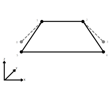
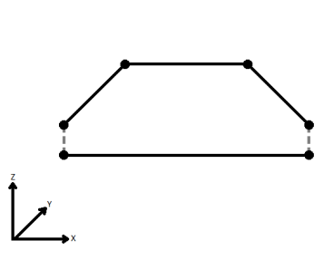
When viewed in 2D (ignoring Z), a path (which may define the border of a polygon) may appear to be closed as shown in the left figure below. This same path, when viewed in 3D, may appear to be open as shown in the right figure below.
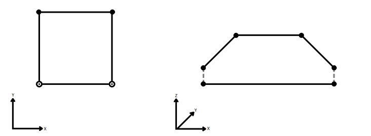
To specify how (and if) paths should be closed in 3D, select one of the listed modes.
| Mode | Description | Example |
|---|---|---|
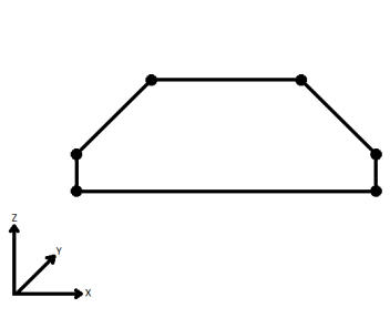
| Extend | The Curve is extended so that all vertices are left at their original location. |
|
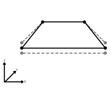
| Average | Subsequent vertices that are not connected, but share an x and a y value are combined into one vertex, whose Z value is the average of the original two. |
|
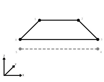
| First Wins | Subsequent vertices that are not connected, but share an x and a y value are combined into one vertex, whose Z value is taken from the first encountered vertex. |
|
| Last Wins | Subsequent vertices that are not connected, but share an x and a y value are combined into one vertex, whose Z value is taken from the last encountered vertex. |
|
| Ignore | Z values are ignored. No change is made to the way the nodes are connected. |
|
If set to Yes, then when lines originating from different input curves are concatenated into a longer curve in the output, they will be left as separate segments in a path. The default is No, which means that such lines will be joined into longer lines in the output unless they have different properties (for example, traits, measures, geometry name).
Choose how aggregate geometries are to be handled.
Deaggregate: Decompose aggregates into their individual components.
Reject: Do not process aggregates and output them via the <Rejected> port.
Usage Notes
- If the data might contain intersecting lines, consider running it through the Intersector before connecting this transformer.
- On common vertices between combined lines, the LineCombiner maintains z-values and measures from the subsequent line.
Example
Editing Transformer Parameters
Using a set of menu options, transformer parameters can be assigned by referencing other elements in the workspace. More advanced functions, such as an advanced editor and an arithmetic editor, are also available in some transformers. To access a menu of these options, click  beside the applicable parameter. For more information, see Transformer Parameter Menu Options.
Transformer Categories
Search FME Knowledge Center
Search for samples and information about this transformer on the FME Knowledge Center.
Tags Keywords: connectivity ring PseudoNodeRemover LineJoiner