Performs a geometric clipping operation (sometimes called a cookie cutter). Most geometry types can be clipped by an area, and some may also be clipped by a solid. Attributes may be shared between objects (spatial join).
Typical Uses
- Identifying where points, lines, or areas fall inside, outside, and intersect with one or more reference areas (Clippers), and modifying their geometry and attributes accordingly.
- Clipping features to perform calculations by Clipper area
- Clipping rasters or point clouds to a regular or irregular area of interest
- Clipping features to a map boundary for aesthetics
How does it work?
The Clipper takes in two sets of features:
- Clippers, which will be overlaid on other features to identify which of those features fall inside or outside the Clippers, and split those features where they cross the boundaries of the Clippers.
The geometry of the Clippers is unchanged, and they are discarded after use and not output from the Clipper transformer. - Clippees, which are compared to the Clippers, and split into multiple sections along the Clipper boundaries if necessary. Each section is output as either falling Inside or Outside the Clipper. They may also receive attributes from the Clippers (spatial join).
Clippee geometry is only altered if it intersects with a Clipper. If it falls wholly inside or outside the Clipper, it is designated as such and output with its geometry untouched.
Output features receive a new Clipped Indicator Attribute (default name _clipped), which is set to “yes” for features that have been segmented, enabling differentiation between features that were wholly inside or outside the clip boundaries and those that intersected the Clipper feature(s) and so were modified.
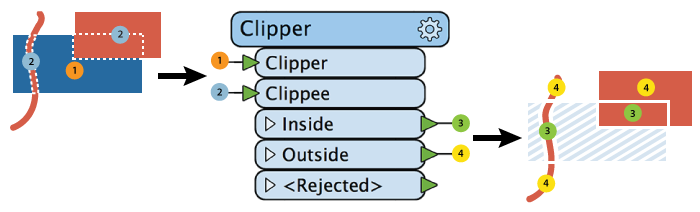
The Clipper works on many geometry types. This diagram illustrates area-on-line and area-on-area vector clipping results.
- (1) is a single area Clipper (in blue).
- (2) are the Clippees, a red line that crosses the Clipper (1), and red area that partially overlays the Clipper (1).
Both the line and area Clippees are split where they cross the Clipper boundary, and the results are output:
- (3) Portions of Clippees that fall Inside the Clipper (red only)
- (4) Portions of Clippees that fall Outside the Clipper (red only)
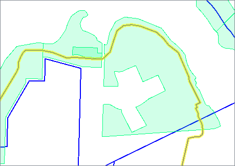
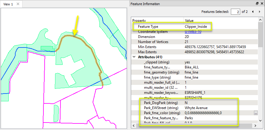
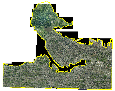
In this example, we start with two datasets - one with multiple park polygons, and the second with bike path lines. The bike paths run in and out of multiple parks, as can be seen here with the path selected and highlighted in yellow.
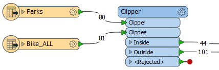
In the workspace, the parks are routed into the Clipper input port, and the bike paths are the Clippees - the features that will be altered according to the Clippers.
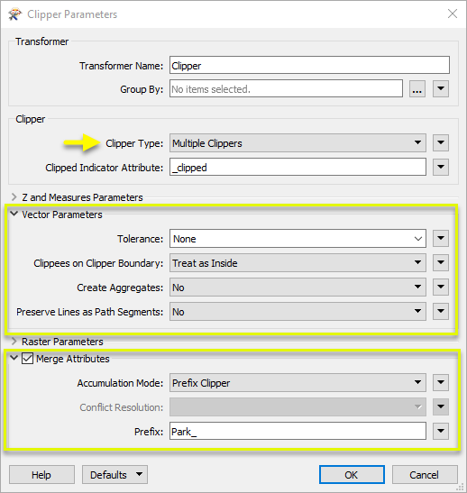
In the Clipper parameters dialog, Clipper Type is set to Multiple Clippers, as we have multiple park polygons and want to clip the paths with all of them.
This is a vector clip, and so we make the appropriate selections under Vector Parameters, including setting Create Aggregates to No - which determines how the output lines are handled.
Lastly, we enable Merge Attributes, which will transfer attributes from the parks (Clippers) to the lines (Clippees). By choosing Prefix Clipper, these new attributes will be prefixed with our string “Park_” and clearly indicate the source of the attribute.
The bike paths are split where they encounter a park boundary, receive attributes prefixed with Park_, and are output as either Inside or Outside feature types (shown here in blue and magenta).
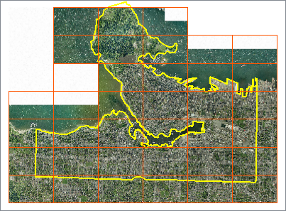
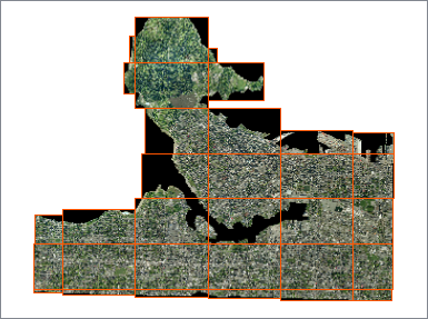
In this example, we have a series of 40 orthophoto tiles, which we would like to clip to the city’s land boundary. The boundaries (extents) of each raster are overlaid in orange.
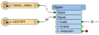
The boundary - a single polygon - is connected to the Clipper input port, and the series of TIFF images are connected to the Clippee port. Note that 40 individual TIFF files are read in, but only 32 will be sent out the Inside output port.
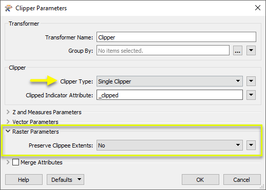
In the Clipper parameters dialog, we set Clipper Type to Single Clipper, which will improve performance in this case, where we do have only one Clipper area.
For a raster clipping operation, the only other parameters we need to look at are Raster Parameters, where we choose whether or not we want areas outside the clip boundary to be padded with nodata pixels to their original extents. No is the default, and fine for this case. (If you want the output rasters to retain their original dimensions, you would choose Yes.)
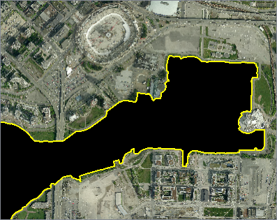
Of the 40 rasters that went in, 32 of them fell partially or entirely Inside the clip boundary. In the rasters that intersected the boundary, pixels that fall inside are untouched, but pixels that fall outside are set to nodata - indicated here by black.
This close-up shows the clipping of pixels (nodata - black) along the water boundary.
The extents of new rasters are shown here in orange. They are of varying size now, clipped tightly to the Clipper boundary (as we chose not to Preserve Clippee Extents).
What can I clip?
As the Clipper collects multiple clipping methodologies into one convenient transformer, it is important to understand which type of clipping you wish to perform, and which types of geometry can be compared in a clipping operation.
Most types can be clipped by an area or multi-area. Some types can also be clipped by a solid or multi-solid.
If the clipping operation you need is not listed here, consider one of the Overlayers or the Intersector- see Choosing a Spatial Transformer below.
|
This: |
Can be clipped by: |
Can clip: |
|---|---|---|
| Point/text |
Area*
Solid** |
Nothing |
| Curve/line | Area* | Nothing |
| Area | Area* |
Point/text
Curve/line Area Solid Point Cloud Raster Multi/aggregates of the above |
| Surface | Nothing | Nothing |
| Solid |
Area*
Solid** |
Point/text
Solid Point Cloud Multi/aggregates of the above |
| Point cloud |
Area*
Solid** |
Nothing |
| Raster | Area* | Nothing |
| Multi-point/aggregate |
Area*
Solid** |
Nothing |
| Multi-curve/aggregate | Area* | Nothing |
| Multi-area/aggregate | Area* |
Point/text
Curve/line Area Solid Point Cloud Raster Multi/aggregates of the above |
| Multi-solid/aggregate |
Area*
Solid** |
Point/text
Solid Point Cloud Multi/aggregates of the above |
| No geometry | Nothing | Nothing |
* Area as Clipper: includes polygons, ellipses, donuts, and aggregates (multi-) of them.
** Solid as Clipper: includes solids and aggregate (multi-) solids.
Usage Notes
- Because a raster feature must always be rectangular, clipped raster cells (i.e. those outside the clipper but part of an Inside raster) will be set to the nodata value. If a nodata value has not been set, clipped raster cells will be set to 0. To set a value for nodata, use the RasterBandNodataSetter transformer prior to the Clipper.
- This transformer is unaffected by raster band and palette selection.
- A feature can be clipped multiple times, but not iteratively (for example, if a line passes through two overlapping polygons, you don’t get a separate clipped line for the overlap - just one per polygon).
For maximum intersectionality, consider the Intersector.
Choosing a Spatial Transformer
Many transformers can assess spatial relationships and perform spatial joins - analyzing topology, merging attributes, and sometimes modifying geometry. Generally, choosing the one that is most specific to the task you need to accomplish will provide the optimal performance results. If there is more than one way to do it (which is frequently the case), time spent on performance testing alternate methods may be worthwhile.
To correctly analyze spatial relationships, all features should be in the same coordinate system. The Reprojector may be useful for reprojecting features within the workspace.
|
Transformer |
Can Merge Attributes |
Alters Geometry |
Counts Related Features |
Creates List |
Supported Types* |
Recommended For |
|---|---|---|---|---|---|---|
| SpatialFilter | Yes | No | No | No |
|
|
| SpatialRelator | Yes | No | Yes | Yes |
|
|
| AreaOnAreaOverlayer | Yes | Yes | Yes | Yes |
|
|
| LineOnAreaOverlayer | Yes | Yes | Yes | Yes |
|
|
| LineOnLineOverlayer | Yes | Yes | Yes | Yes |
|
|
| PointOnAreaOverlayer | Yes | No | Yes | Yes |
|
|
| PointOnLineOverlayer | Yes | Yes | Yes | Yes |
|
|
| PointOnPointOverlayer | Yes | No | Yes | Yes |
|
|
| Intersector | Yes | Yes | Yes | Yes |
|
|
| Clipper | Yes | Yes | No | No |
|
|
| NeighborFinder | Yes | In some cases | No | Yes |
|
|
| TopologyBuilder | Yes | Yes | No | Yes |
|
|
* NOTE: Curve includes Lines, Arcs, and Paths. Area includes Polygons, Donuts, and Ellipses.
Spatial analysis can be processing-intensive, particularly when a large number of features are involved. If you would like to tune the performance of your workspace, this is a good place to start.
When there are multiple ways to configure a workspace to reach the same goal, it is often best to choose the transformer most specifically suited to your task. As an example, when comparing address points to building polygons, there are a few ways to approach it.
The first example, using a SpatialFilter to test whether or not points fall inside polygons, produces the correct result. But the SpatialFilter is a fairly complex transformer, able to test for multiple conditions and accept a wide range of geometry types. It isn’t optimized for the specific spatial relationship we are analyzing here.
With a SpatialFilter:
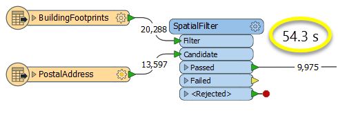
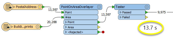
The second example uses a PointOnAreaOverlayer, followed by a Tester. The features output are the same as in the first method, but the transformer is optimized for this specific task. The difference in processing time is substantial - from 54.3 seconds in the first configuration, down to 13.7 seconds in the second one.
With a PointOnAreaOverlayer and a Tester:
If performance is an issue in your workspace, look for alternative methods, guided by geometry.
Configuration
Input Ports
The features routed into the transformer via the Clipper port identify the area against which all Clippee features are processed. The Clipper can consist of any area features (polygons, donuts, or aggregate polygons/donuts). The Clipper can also be a solid or multi-solid if the Clippee input consists of solids, points, point clouds, or aggregates of these geometries. Any invalid clipping features that are encountered will be logged with a warning and discarded.
Features to be clipped enter via the Clippee port.
Output Ports
Clippee features that are completely within the Clipper, and Clippee features that intersect the Clipper which were broken up into pieces. Those pieces that are on the inside of the Clipper are output via this port.
Clippee features completely outside of the Clipper are output via the Outside port, and Clippee features that intersect the Clipper which were broken up into pieces. Those pieces that are outside the clipping area are output via this port.
Invalid Clipper features (that is, non-polygon features) as well as invalid Clippee features (that is, features with no geometry) are output via the <Rejected> port.
Rejected features will have an fme_rejection_code attribute with one of the following values:
EXTRA_CLIPPER_FEATURE
INVALID_CLIPPER_GEOMETRY_TYPE.
Rejected Feature Handling: can be set to either terminate the translation or continue running when it encounters a rejected feature. This setting is available both as a default FME option and as a workspace parameter.
Parameters
| Group By | The default behavior is to use the entire set of features as the group. This option allows you to select attributes that define which groups to form. |
| Clipper Type |
Single Clipper: Only a single Clipper feature will be used. Multiple Clippers: All Clipper features will be used. Clippers First: The Clipper assumes that all Clipper features will enter the transformer before any Clippee features. Any further Clipper features that arrive after the first Clippee will be logged with a warning and discarded. |
| Clipped Indicator Attribute | This attribute (if specified) will be added with a value of yes to any features output via either the Inside or Outside port which were cut by the transformer, and a value of no to any output features which were not changed by the transformer. |
| Preserve Measures/Z From |
Specifies where to take the measures and Z values from. Clippee Only: All measures and Z values of the Clipper will be dropped. Clipper Only: All measures and Z values from the Clippee will be dropped. Clipper and Clippee: Measures and Z values from the Clippee and Clipper are used. The Connect Z Mode parameter will determine how z values are handled. |
||||||||||||||||||
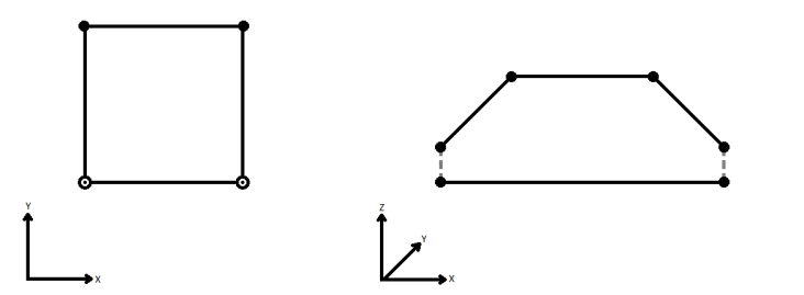
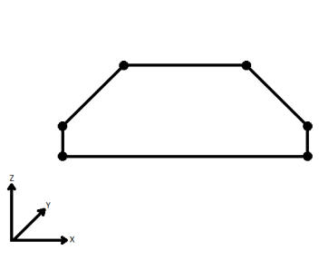
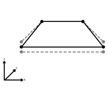
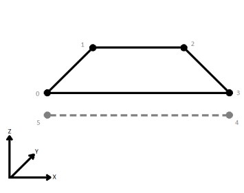
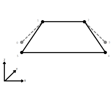
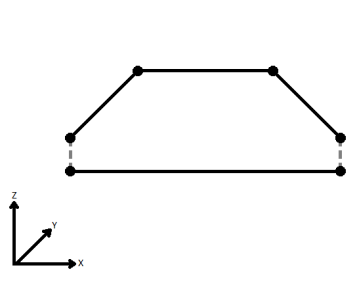
| Connect Z Mode |
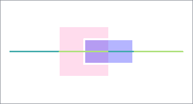
If applicable, select a method for handling z values. When viewed in 2D (ignoring Z), a path (which may define the border of a polygon) may appear to be closed as shown in the left figure below. This same path, when viewed in 3D, may appear to be open as shown in the right figure below.
To specify how (and if) paths should be closed in 3D, select one of the listed modes.
|
||||||||||||||||||
| Measures/Z Conflict Value |
This parameter specifies how to deal with geometries that have a measure, but are missing at least one value, or that have z values, but are missing at least one value. None (Drop Values): Remove incomplete measures or z values. Compute: Look at the values on either side of the missing value, and compute an estimate. Custom Value: The missing values are filled in with the specified custom default value. |
||||||||||||||||||
| Treat Measures as | When using the Compute mode to compute missing measure values, measures can be considered Continuous, and linearly interpolated from their neighbors, or they can be Discrete, and taken exactly from the nearest neighbor. |
| Tolerance |
The minimum distance between geometries in 2D before they are considered equal, in ground units. If the tolerance is None, the geometries must be exactly identical to be considered equal. If the tolerance is Automatic, a tolerance will be automatically computed based on the location of the input geometries. Additionally, a custom tolerance may be used. |
| Clippees on Clipper Boundary |
This parameter directs what action should be taken with Clippee features that lie entirely on the boundary of the clipper. Treat as Inside: These features that lie on the boundary are output via the Inside port. Treat as Outside: These features that lie on the boundary are output via the Outside port. Treat as Inside and Outside: Points and line segments on the boundary are duplicated and output as both Inside and Outside. |
| Create Aggregates | If the Create Aggregates parameter is No, then features that are clipped into multiple parts will not be aggregated, but rather each part will be output as a separate feature. |
| Preserve Lines as Path Segments |
Yes: Contiguous lines that constitute the boundary of the output features will be left as separate segments in a path. No: Such lines will be joined into longer lines in the output unless they have different properties (for example, traits, measures, and geometry name). |
| Preserve Clippee Extents | If this parameter is set to No, the Inside rasters which were clipped will be equal to the intersections of the clippers and clippees. Otherwise, the intersections will be padded by nodata so that the extents are identical to those of the input rasters. |
When enabled, attributes on the Clipper will be merged onto the Clippee as defined by the parameters here. Otherwise, no attribute merging will take place.
If attributes on the Clipper and Clippee features share the same name, but are not geometry attributes that start with fme_, then they are deemed conflicted.
| Accumulation Mode |
Merge Clipper: The Clippee feature will retain all of its own un-conflicted attributes, and will additionally acquire any un-conflicted attributes that the Clipper feature has. This mode will handle conflicted attributes based on the Conflict Resolution parameter. Prefix Clipper: The Clippee feature will retain all of its own attributes. In addition, the Clippee will acquire attributes reflecting the Clipper feature’s attributes, with the name prefixed with the Prefix parameter. Only Use Clipper: The Clippee feature will have all of its attributes removed, except geometry attributes that start with fme_. Then, all of the attributes from one (arbitrary) Clipper feature will be placed onto the Clippee. |
| Conflict Resolution |
Use Clippee: If a conflict occurs, the Clippee values will be maintained. Use Clipper: If a conflict occurs, the values of the Clipper will be transferred onto the Clippee. |
| Prefix | If the Accumulation Mode parameter is set to Prefix Clipper, this value will prefix attributes that are being added to the Clippee feature from the Clipper feature. |
Editing Transformer Parameters
Using a set of menu options, transformer parameters can be assigned by referencing other elements in the workspace. More advanced functions, such as an advanced editor and an arithmetic editor, are also available in some transformers. To access a menu of these options, click  beside the applicable parameter. For more information, see Transformer Parameter Menu Options.
Defining Values
There are several ways to define a value for use in a Transformer. The simplest is to simply type in a value or string, which can include functions of various types such as attribute references, math and string functions, and workspace parameters. There are a number of tools and shortcuts that can assist in constructing values, generally available from the drop-down context menu adjacent to the value field.
Using the Text Editor
The Text Editor provides a convenient way to construct text strings (including regular expressions) from various data sources, such as attributes, parameters, and constants, where the result is used directly inside a parameter.
Using the Arithmetic Editor
The Arithmetic Editor provides a convenient way to construct math expressions from various data sources, such as attributes, parameters, and feature functions, where the result is used directly inside a parameter.
Conditional Values
Set values depending on one or more test conditions that either pass or fail.
Parameter Condition Definition Dialog
Content
Expressions and strings can include a number of functions, characters, parameters, and more - whether entered directly in a parameter or constructed using one of the editors.
| These functions manipulate and format strings. | |
| A set of control characters is available in the Text Editor. | |
| Math functions are available in both editors. | |
| These operators are available in the Arithmetic Editor. | |
| These return primarily feature-specific values. | |
| FME and workspace-specific parameters may be used. | |
| Working with User Parameters | Create your own editable parameters. |
Reference
|
Processing Behavior |
|
|
Feature Holding |
Yes |
| Dependencies | |
| FME Licensing Level | FME Professional Edition and above |
| Aliases | |
| History | |
| Categories |
FME Knowledge Center
The FME Knowledge Center is the place for demos, how-tos, articles, FAQs, and more. Get answers to your questions, learn from other users, and suggest, vote, and comment on new features.
Search for all results about the Clipper on the FME Knowledge Center.
Examples may contain information licensed under the Open Government Licence – Vancouver