FME Transformers: 2025.0
Replaces geometry with an optimal path of line segments and arcs, creating smooth, curving lines and areas.
Typical Uses
-
Optimizing file size or processing by reducing vertices
-
Smoothing jagged geometry
-
Restoring stroked arcs
How does it work?
The CurveFitter receives line and area features and replaces their geometry with a path composed of lines and arcs.
An optimal path is calculated based on a number of parameters:
-
Precision - the maximum amount the new geometry may deviate from the original.
-
Flattening - allows shallow curves to be converted to straight line segments.
-
Weighting - Compression, Smoothness, and Accuracy Weight may be adjusted to emphasize desired outcomes.
Adjacent area boundaries may be preserved, preventing the introduction of gaps and overlaps.
Examples
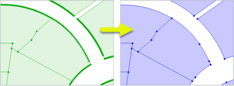
In this example, we have a set of parcel polygons. Note that the curved boundaries have been stroked at some point, and are composed of many small line segments. We want to restore them to arc geometry.
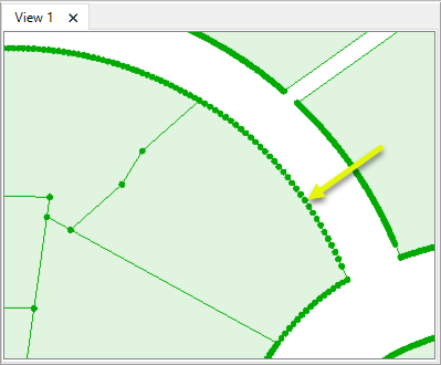
The features are routed into a CurveFitter.

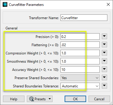
In the parameters dialog, Precision is set to 0.2 meters, with Flattening at 10% of that value.
Weighting is slightly adjusted - Accuracy Weight is increased to the maximum value of 10, emphasizing positional accuracy over smoothness and compression.
Preserved Shared Boundaries is set to Yes, to avoid creating gaps or overlaps where parcel boundaries touch.
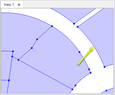
The output feature boundaries are paths composed of line segments and arcs.
Determining the parameter settings to produce a desired result often requires some trial and error. Overlaying the original feature with the CurveFitter output in the Data Inspector can be useful while refining parameter values.
In this example, we have a line with 85 straight segments, representing an engineered feature such as a road. The feature was likely originally defined by arcs and lines.
Since roads are usually engineered as a series of tangent segments, our goal is to produce smooth and positionally accurate geometry (as opposed to reducing points for compression).

In the parameters dialog, Precision is set to a first best guess of 0.5 meters with Flattening at 10% of the Precision value - 0.05.
The Weighting parameters (Compression, Smoothness, and Accuracy) are left with their default balanced values of 1.0.
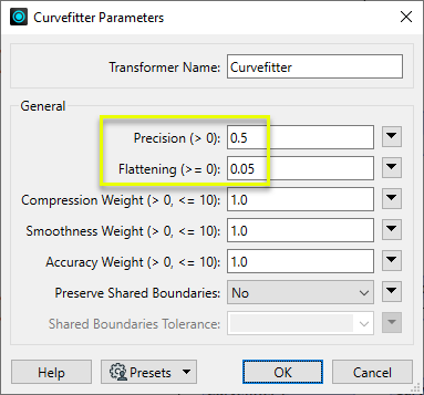
The output feature is a path composed of three arcs. Note that the left and center segments have a fairly smooth transition, but the center and right segments are visibly not tangent.


Using a tighter Precision value of 0.2 meters produces a path with four arc segments. It fits the original feature more closely and is somewhat (but not perfectly) smooth.


To further refine the output geometry, we will adjust the weighting parameters - Compression, Smoothness, and Accuracy. By default, they are equally balanced. We will tune them towards our desired outcome (smooth and accurate), with less emphasis on point reduction (compression).
Compression Weight is reduced to 0.1, while Smoothness Weight is increased to its maximum value of 10.
Accuracy Weight remains at 1.0, and the Precision value still keeps the geometry within 0.2 meters of its original location.
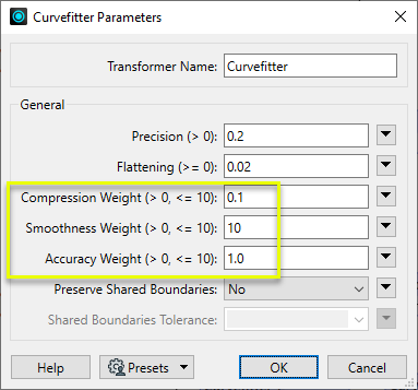
The resulting path is nearly perfectly smooth and still accurate to within 0.2 meters.


Usage Notes
-
In general, arcs do not reproject well. Consider using the ArcStroker prior to reprojecting arcs.
-
In some cases such as working with contours, the Generalizer and its numerous Algorithm choices may be a better choice of transformer.
-
Not all formats support path geometry, and so CurveFitter results may be stroked when writing to them. The PathSplitter can be used to break a path into its component lines and arcs. See Path geometry.
Creating and Modifying Arcs, Circles, and Ellipses
These transformers work with arcs in a variety of ways.
|
Transformer |
Use this to... |
Geometry Out |
Z Coordinates |
|---|---|---|---|
|
Create one or more new features with arc geometry (when Geometry Object is an arc type). |
Arc by center point Arc by center point with ends Arc by 3 points Arc by bulge Ellipse (Arc by center point) |
Supported |
|
|
Replace any existing feature’s geometry with a 2D arc. |
Arc by center point |
No |
|
|
Replace any existing feature’s geometry with a 3D arc. |
Arc by center point |
Yes, at center point |
|
|
Replace an existing feature’s geometry with a 2D ellipse or circle (closed arc). |
Ellipse (Arc by center point) |
No |
|
|
Modify an existing arc or convert a point to an arc. |
Arc by center point Arc by center point with ends Arc by 3 points |
Supported, at center and/or ends |
|
|
Modify an existing ellipse (closed arc) or convert a point to an ellipse. |
Ellipse (Arc by center point) |
Supported, at center point |
|
|
Extract the property values that describe an arc’s geometry and store them as attributes. |
Arc by center point Arc by center point with ends Arc by 3 points Arc by bulge |
Supported |
|
|
Extract the property values that describe an ellipse’s geometry and store them as attributes. |
Ellipse (Arc by center point) |
Supported |
|
|
Convert arcs and ellipses to lines or polygons by interpolating points along the arc. |
Path Line Area |
Supported |
|
|
Replace geometry with an arc described by the first, middle, and last vertices of the input feature. |
Arc by 3 points |
Supported |
|
|
Replace lines or polygons with an optimal combination of line and arc segments, creating smooth curving lines. |
Path Area Arc by bulge Line |
Supported |
|
|
Reduce point density on lines or polygons, fitting arcs where possible (When using Algorithm > Douglas With Arc Fitting (Generalize) ). |
Path Area Arc by 3 points Line |
Supported |
|
|
Either replace an existing feature’s geometry with circle that contains all of its vertices or extract the circle property values into attributes. |
Ellipse (Arc by center point) |
No |
Configuration
Input Ports
Features with line or area geometry.
Output Ports
Features with optimized path geometry as specified in parameters.
Features with geometry other than valid line or area geometry are output via this port, as are features that receive non-numeric values for any numeric parameters.
Rejected features will have an fme_rejection_code attribute with one of the following values:
INVALID_PARAMETER_PRECISION
INVALID_PARAMETER_FLATTENING
INVALID_PARAMETER_COMPRESSION_WEIGHT
INVALID_PARAMETER_SMOOTHNESS_WEIGHT
INVALID_PARAMETER_ACCURACY_WEIGHT
INVALID_PARAMETER_GENERALIZATION_TOLERANCE
INVALID_GEOMETRY_TYPE
Rejected Feature Handling: can be set to either terminate the translation or continue running when it encounters a rejected feature. This setting is available both as a default FME option and as a workspace parameter.
Parameters
|
Precision |
Specify the maximum distance in ground units that the new geometry may deviate from the original. |
|
Flattening |
Determines the flattening of shallow curves. Specify the maximum arc mid-ordinate distance below which curves may be converted to straight lines. A typical value is 10% of the Precision value. |
|
Compression Weight
|
Three weighting factors are considered when calculating the new path. They are balanced by default but may be adjusted to emphasize different outcomes.
Specify a value for each one, greater than zero (0) and less then or equal to 10. By default all three are set to 1.0. |
|
Smoothness Weight |
See Compression Weight. |
|
Accuracy Weight |
See Compression Weight. |
|
Preserve Shared Boundaries |
Select a method for processing adjacent areas, if present:
If only linear or non-adjacent area features are input into the transformer, No is the more efficient choice. |
|
Shared Boundaries Tolerance |
When Preserved Shared Boundaries is Yes, specify the distance between two boundaries (in 2D) below which they are considered shared. If Automatic, an appropriate tolerance is computed based on the input features. |
Editing Transformer Parameters
Transformer parameters can be set by directly entering values, using expressions, or referencing other elements in the workspace such as attribute values or user parameters. Various editors and context menus are available to assist. To see what is available, click  beside the applicable parameter.
Defining Values
There are several ways to define a value for use in a Transformer. The simplest is to simply type in a value or string, which can include functions of various types such as attribute references, math and string functions, and workspace parameters.
Using the Text Editor
The Text Editor provides a convenient way to construct text strings (including regular expressions) from various data sources, such as attributes, parameters, and constants, where the result is used directly inside a parameter.
Using the Arithmetic Editor
The Arithmetic Editor provides a convenient way to construct math expressions from various data sources, such as attributes, parameters, and feature functions, where the result is used directly inside a parameter.
Conditional Values
Set values depending on one or more test conditions that either pass or fail.
Parameter Condition Definition Dialog
Content
Expressions and strings can include a number of functions, characters, parameters, and more.
When setting values - whether entered directly in a parameter or constructed using one of the editors - strings and expressions containing String, Math, Date/Time or FME Feature Functions will have those functions evaluated. Therefore, the names of these functions (in the form @<function_name>) should not be used as literal string values.
| These functions manipulate and format strings. | |
|
Special Characters |
A set of control characters is available in the Text Editor. |
| Math functions are available in both editors. | |
| Date/Time Functions | Date and time functions are available in the Text Editor. |
| These operators are available in the Arithmetic Editor. | |
| These return primarily feature-specific values. | |
| FME and workspace-specific parameters may be used. | |
| Creating and Modifying User Parameters | Create your own editable parameters. |
Table Tools
Transformers with table-style parameters have additional tools for populating and manipulating values.
|
Row Reordering
|
Enabled once you have clicked on a row item. Choices include:
|
|
Cut, Copy, and Paste
|
Enabled once you have clicked on a row item. Choices include:
Cut, copy, and paste may be used within a transformer, or between transformers. |
|
Filter
|
Start typing a string, and the matrix will only display rows matching those characters. Searches all columns. This only affects the display of attributes within the transformer - it does not alter which attributes are output. |
|
Import
|
Import populates the table with a set of new attributes read from a dataset. Specific application varies between transformers. |
|
Reset/Refresh
|
Generally resets the table to its initial state, and may provide additional options to remove invalid entries. Behavior varies between transformers. |
Note: Not all tools are available in all transformers.
For more information, see Transformer Parameter Menu Options.
Reference
|
Processing Behavior |
|
|
Feature Holding |
No, except when Preserve Shared Boundaries is Yes. |
| Dependencies | None |
| Aliases | |
| History | Formerly an extra-cost add-on. |
FME Community
The FME Community has a wealth of FME knowledge with over 20,000 active members worldwide. Get help with FME, share knowledge, and connect with users globally.
Search for all results about the CurveFitter on the FME Community.
Examples may contain information licensed under the Open Government Licence – Vancouver, Open Government Licence - British Columbia, and/or Open Government Licence – Canada.


