|
Database formats include a Database Connection parameter that defines and stores authentication information. For general information about sharing database connections, please see Using Database Connections. Note that Database Connection parameters differ slightly, depending on context and/or database format. |
|
Connection From the Connection parameter in a database format, you can do one of the following:
|
Database Connection
Select the Esri File Geodatabase source folder.
Constraints
This parameter specifies whether or not the feature dataset should be read.
If checked, the feature dataset will not be included in the Select Tables dialog or as part of the feature type.
After specifying the database connection, click the Browse button (...) to select tables for import. A connection window appears while the system retrieves the tables from the database.
Once the Select Tables dialog appears, you can select one or more tables. Click OK to dismiss the window and add the selected table name(s) to the Tables parameter.
Schema Attributes
Use this parameter to expose Format Attributes in FME Workbench when you create a workspace:
- In a dynamic scenario, it means these attributes can be passed to the output dataset at runtime.
- In a non-dynamic scenario, this parameter allows you to expose additional attributes on multiple feature types. Click the browse button to view the available format attributes (which are different for each format) for the reader.
Spatial
Coordinate systems may be extracted from input feature data sources, may come predefined with FME, or may be user-defined. FME allows different output and input coordinate systems, and performs the required coordinate conversions when necessary.
If a coordinate system is specified in both the source format and the workspace, the coordinate system in the workspace is used. The coordinate system specified in the source format is not used, and a warning is logged. If a source coordinate system is not specified in the workspace and the format or system does not store coordinate system information, then the coordinate system is not set for the features that are read.
If a destination coordinate system is set and the feature has been tagged with a coordinate system, then a coordinate system conversion is performed to put the feature into the destination system. This happens right before the feature enters into the writer.
If the destination coordinate system was not set, then the features are written out in their original coordinate system.
If a destination coordinate system is set, but the source coordinate system was not specified in the workspace or stored in the source format, then no conversion is performed. The features are simply tagged with the output system name before being written to the output dataset.
For systems that know their coordinate system, the Coordinate System field will display Read from Source and FME will read the coordinate system from the source dataset. For most other input sources, the field will display Unknown (which simply means that FME will use default values). In most cases, the default value is all you'll need to perform the translation.
You can always choose to override the defaults and choose a new coordinate system. Select More Coordinate Systems from the drop-down menu to open the Coordinate System Gallery.
Changing a Reprojection
To perform a reprojection, FME typically uses the CS-MAP reprojection engine, which includes definitions for thousands of coordinate systems, with a large variety of projections, datums, ellipsoids, and units. However, GIS applications have slightly different algorithms for reprojecting data between different coordinate systems. To ensure that the data FME writes matches exactly to your existing data, you can use the reprojection engine from a different application.
To change the reprojection engine, Select Workspace Parameters > Spatial > Reprojection Engine. In the example shown, you can select Esri (but the selection here depends on your installed applications):

- The coordinate systems file coordsys.db in the FME installation folder contains the names and descriptions of all predefined coordinate systems.
- Some users may wish to use coordinate systems that do not ship with FME, and in those cases, FME also supports custom coordinate systems.
- Learn more about Working with Coordinate Systems in FME.
Geometry
When creating donut geometries, this parameter specifies the criteria that FME will use to detect the geometric properties of the donut(s).
- Orientation Only – FME will detect donut geometry only based on orientation of the rings. Shapefile specifications state that outer boundaries of donut geometries must have clockwise orientation, and any donut holes must have counter-clockwise orientation. This option shall preserve the order of the areas.
- Orientation and Spatial Relationship – FME will detect donut geometry initially by orientation, and will perform additional geometric validation by analyzing the spatial relationships between the donut’s outer rings and holes. If any invalid donut geometries are identified, FME will attempt to correct geometric anomalies (for example, holes larger than outer ring, holes within holes, etc.). If your dataset is supposed to have holes but FME does not correctly produce them, select Orientation and Spatial Relationship.
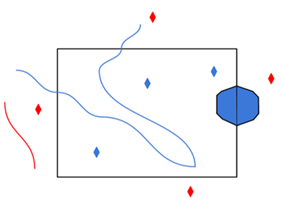
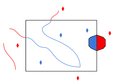
A search envelope (also known as a bounding box) is a rectangular area that defines a geographic area. In FME, the easiest way to define a search envelope is to use search envelope parameters.
Defining a search envelope is the most efficient method of selecting an area of interest because FME will read only the data that is necessary – it does not have to read an entire dataset. Search Envelope parameters apply to both vector and raster datasets and can be particularly efficient if the source format has a spatial index.
Most FME readers have parameters to define the search envelope of data that is being read:
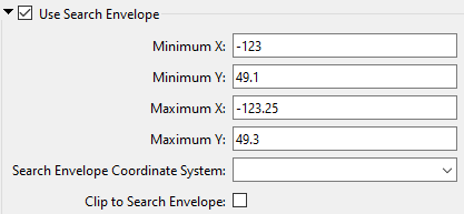
The parameters include the x and y coordinates of the bounding box as well as a parameter that defines the coordinate system.
How to Define the Bounding Box
Using the minimum and maximum x and y parameters, define a bounding box that will be used to filter the input features. Only features that intersect with the bounding box are returned. Note that the bounding box intersection is not a full geometry intersection (based on spatial relationships) that would be returned by a transformer like the SpatialFilter.
|
Search Envelope Coordinate System |
Specifies the coordinate system of the search envelope if it is different than the coordinate system of the data. The coordinate system associated with the data to be read must always be set if this parameter is set. If this parameter is set, the minimum and maximum points of the search envelope are reprojected from the Search Envelope Coordinate System to the reader’s coordinate system prior to applying the envelope. |
||||||
|
Clip to Search Envelope |
The underlying function for Use Search Envelope is an intersection; however, when Clip to Search Envelope is checked, a clipping operation is also performed.
|

In some programs (for example, ArcGIS Pro), GlobalID and GUID attributes contain braces:

When set to Yes, this parameter removes the braces from the GlobalID and GUID attributes for compatibility with programs where these attributes do not contain braces.
The default is No.
When inserting into a table, Row Selection is ignored. When updating and deleting from a table (if applicable, based on a format's available Feature Operation options), a condition needs to be specified for selecting which rows to operate on. This parameter group offers two methods to construct the selection condition:
Match Columns
The columns specified in the corresponding column picker dialog will be used for matching destination rows. All matching rows will be selected for update or delete. If any feature attributes corresponding to the specified match columns contain null or missing values, the feature will be rejected.
WHERE Clause
This parameter opens a WHERE Clause Builder. You can also type a WHERE clause inline, without launching the Builder. It is optional to start the clause with the word WHERE.
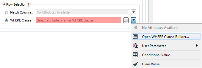
The WHERE Clause Builder makes it easy for users to reference feature attribute values, destination table columns, and invoke FME functions. The WHERE clause is first evaluated as an FME expression, before being passed onto the destination database.
If the WHERE clause is incorrect or if its evaluation results in failure, the translation will fail. Otherwise, if the WHERE clause passes FME evaluation but it is SQL invalid, the feature will be rejected or the translation will fail.
For advanced users, conditional FME expressions created through the Conditional Value editor can be used to create WHERE clauses.
Advanced
This parameter allows for the execution of SQL statements before opening a table for reading. For example, it may be necessary to create a temporary view before attempting to read from it.
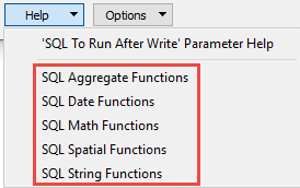
For detailed information about SQL functions, click the corresponding menu item in the SQL to Run editor help
 .
.
 to open the editor.
Available menu options depend on the format.
Multiple SQL commands can be delimited by a character specified using the FME_SQL_DELIMITER directive, embedded at the beginning of the SQL block. The single character following this directive will be used to split the SQL block into SQL statements, which will then be sent to the database for execution. Note: Include a space before the character.
For example:
FME_SQL_DELIMITER ;
DELETE FROM instructors ;
DELETE FROM people
WHERE LastName='Doe' AND FirstName='John'
Multiple delimiters are not allowed and the delimiter character will be stripped before being sent to the database.
Any errors occurring during the execution of these SQL statements will normally terminate the reader or writer (depending on where the SQL statement is executed) with an error. If the specified statement is preceded by a hyphen (“-”), such errors are ignored.
This parameter allows for the execution of SQL statements after a set of tables has been read. For example, it may be necessary to clean up a temporary view after creating it.
For detailed information about SQL functions, click the corresponding menu item in the SQL to Run editor help.
to open the editor.Available menu options depend on the format.
Multiple SQL commands can be delimited by a character specified using the FME_SQL_DELIMITER directive, embedded at the beginning of the SQL block. The single character following this directive will be used to split the SQL block into SQL statements, which will then be sent to the database for execution. Note: Include a space before the character.
For example:
FME_SQL_DELIMITER ;
DELETE FROM instructors ;
DELETE FROM people
WHERE LastName='Doe' AND FirstName='John'
Multiple delimiters are not allowed and the delimiter character will be stripped before being sent to the database.
Any errors occurring during the execution of these SQL statements will normally terminate the reader or writer (depending on where the SQL statement is executed) with an error. If the specified statement is preceded by a hyphen (“-”), such errors are ignored.