Reprojects feature coordinates from one coordinate system to another using the CS-MAP library.
Typical Uses
- Reprojecting features when explicitly using the CS-Map library is desired
- Reprojecting coordinates with Z values (except raster)
- Performing reprojections with finer control than the Reprojector or inherent reprojections provide
How does it work?
The CsmapReprojector receives vector, raster, or point cloud features and reprojects their coordinates from one coordinate system to another, using the CS-Map library.
The CS-Map library is FME’s default library, and so is generally used for most transformations. Using this transformer explicitly ensures that this library is used, and also provides options for handing Z (vertical) values.
The Source Coordinate System may be either read from the input feature or specified explicitly, and the Destination Coordinate System must be specified. Both may be set by selecting from the Coordinate System Gallery or by name via an attribute value or user parameter.
Dynamic Coordinate Systems
Features may be reprojected to a dynamic Destination Coordinate System - that is, a local coordinate system that is created specifically for each individual feature. This is often used for tasks such as taking measurements or creating geometry in meters or other ground units, on data with geographic (latitude and longitude) coordinates.
There are two types available:
- _AZMEA_ (Dynamic Reprojection Equal Area) - Better for preserving area accuracy
- _AZMED_ (Dynamic Reprojection Equal Distance) - Better for preserving distance accuracy
In either case, the input feature is reprojected to a local coordinate system centered on its bounding box. Though all the output features will be centered on a common origin (with the exception of features located very near the poles) and appear stacked on top of each other, each one retains the specifics of its reprojection (and so original position), and can be safely reprojected back into a projected or geographic coordinate system.
Note that Z values are not considered, so areas or distances are best preserved for geometry at an ellipsoid height of 0 meters.
Note: To calculate and reproject to a single AZMED or AZMEA coordinate system that encompasses all input features, consider using the CommonLocalReprojector.
Geographic Transformations
Geographic Transformations control how coordinates are converted between different datums.
The default Transformation is <Auto> (or blank), which will look for an appropriate transformation between datums, if one is needed.
If an explicitly selected pair of coordinate systems has one or more geographic transformations available, they will be provided for explicit selection.
If set to <None>, the NULL_FME transformation will be used which does not alter the value of any coordinates.
Rasters
Additional parameters are available for raster features, specifying how the reprojected cells are to be interpolated.
This transformer is not affected by raster band and palette selection.
Examples
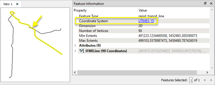
In this example, we have a shapefile of transit lines, projected in the coordinate system UTM83-10 - UTM Zone 10, NAD83 (North American Datum 1983).
We want to reproject them into an older datum - NAD27.
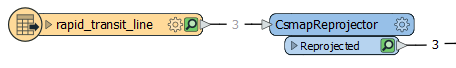
The features are routed into a CsmapReprojector.
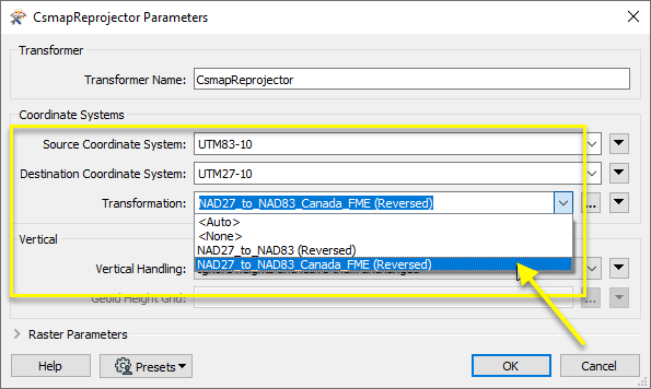
In the parameters dialog, both the Source and Destination Coordinate Systems are explicitly defined.
Though we could leave the Source Coordinate System as <Read from feature>, explicitly defining both of them gives us access to the available Transformations for that combination of coordinate systems. There are two, and we select the Canadian one for this dataset. Note that the direction is Reversed since we are going from the newer datum to the older one.
If we had previously set a preference in FME Options > Coordinate Systems > Implicit Transformations to either Canada Only or USA Only, the <Auto> Transformation option would use that setting.
The data is 2D, so Vertical Handling is left as Ignore heights and leave them unchanged.
The output features are reprojected to UTM27-10.
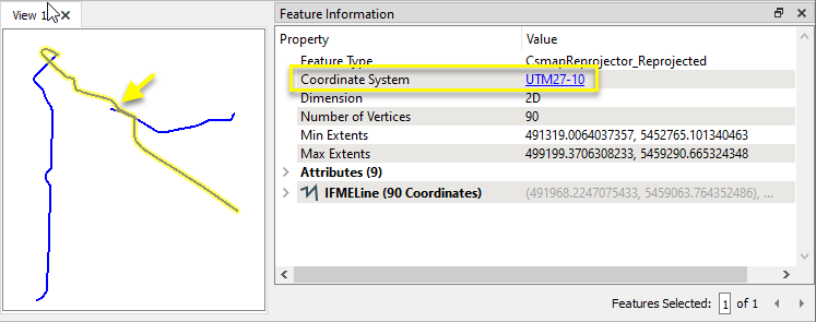
Examining both the input (red) and output (blue) features overlaid in the FME Data Inspector (with the Background Map OFF), we can see the results of the datum shift, based on the Canadian NTv2 grid shift file.

Usage Notes
- FME also has a Workspace Parameter, Reprojection Engine, that may be set to either FME (CS-Map) or Esri. This transformer will override this parameter setting.
- The Reprojector provides similar functionality, and will use the default library (CS-Map or Esri) set in FME. It does not handle z values.
- To reproject coordinates stored as attribute values, consider using the CsmapAttributeReprojector.
Working With Coordinate System Transformers
FME inherently supports coordinate system transformations and reprojections.
Coordinate systems generally have a name and a definition, and the syntax of that definition can vary greatly between both spatial data formats and other coordinate system libraries. Custom and local coordinate systems can also be defined in FME, further complicating matters. For in-depth information, see the Working With Coordinate Systems documentation.
Reprojections are generally done with the FME Reprojection Engine, which is based on the CS-Map coordinate system library. This default can be overridden on a per-workspace basis, using the Workspace Parameters > Translation > Reprojection Engine parameter, and set to Esri. Where appropriate, FME will use the Esri Reprojection Engine if it is selected there, with or without an Esri product being installed.
Coordinate System Support
These transformers perform various coordinate system-related tasks, but do not reproject the data.
|
Looks up coordinate system names and definitions between FME’s internal format and common third-party and open source representations, storing the results as an attribute. |
|
|
Retrieves the name of the feature's assigned FME coordinate system into an attribute. |
|
|
Removes the coordinate system from features, without modifying geometry or coordinates. |
|
|
Assigns a specified coordinate system to features, without modifying geometry or coordinates. |
|
|
Assigns a specified local coordinate system to features, without modifying geometry or coordinates. |
Coordinate System Reprojection
Different coordinate system libraries (engines) not only contain coordinate system definitions, they also have unique reprojection algorithms. FME’s generic reprojection transformers, in the first table below, default to using the FME (CS-Map) library.
A selection of other libraries is also available, some of which are specific to certain areas of the world or software platforms.
Inherent reprojections, as in a workspace with different input and output coordinate systems selected, default to using the FME (CS-Map) library.
If you are reprojecting explicitly with a transformer in the workspace, using library-specific transformers is recommended. In the case of CsmapReprojector versus the Reprojector (with default engine), the library may be identical, but the CSMapReprojector handles vertical coordinate calculations whereas the Reprojector does not.
Generic Reprojection Transformers
|
|
|
Library |
|---|---|---|
|
Reprojects x and y coordinates stored as attributes from one coordinate system to another. |
FME (default) or Esri |
|
|
Reprojects one or more features to a local coordinate system centered on the bounding box containing all features. |
FME (default) or Esri |
|
|
Converts a given angle from one coordinate system to another. |
FME (default) or Esri |
|
|
Converts a given length from one coordinate system to another. |
FME (default) or Esri |
|
|
Reprojects feature x and y coordinates from one coordinate system to another. |
FME (default) or Esri |
Library-Specific Reprojection Transformers (Recommended)
|
|
|
Library (External Links) |
|---|---|---|
|
Reprojects x, y, and optionally z coordinates stored as attributes from one coordinate system to another using the CS-MAP library. |
||
|
Reprojects feature x, y, and optionally z coordinates from one coordinate system to another using the CS-Map library. |
||
|
Reprojects feature coordinates from one coordinate system to another using the Esri reprojection library. |
||
|
Great Britain Northern Ireland Republic of Ireland |
Reprojects feature coordinates from one coordinate system to another using the Grid InQuestII engine from Ordnance Survey, for use in Great Britain, Ireland, and Northern Ireland. |
|
|
Sweden |
Reprojects coordinates stored as attributes from one coordinate system to another using the Gtrans reprojection engine from the National Land Survey of Sweden (Lantmäteriet). |
|
|
Sweden |
Reprojects feature coordinates from one coordinate system to another using the Gtrans reprojection engine from the National Land Survey of Sweden (Lantmäteriet). |
|
|
Reprojects coordinates stored as attributes from one coordinate system to another using the PROJ library. |
||
|
Reprojects feature coordinates from one coordinate system to another using the PROJ library. |
||
|
Switzerland |
Reprojects feature coordinates from one coordinate system to another in Switzerland, using the Reframe library from the Federal Office of Topography (swisstopo). |
Configuration
Input Ports
This transformer accepts any feature.
Output Ports
Features reprojected as specified in parameters.
Parameters
|
Source Coordinate System |
Specify the coordinate system of the incoming features. The default is <Read from feature>, which reads the features’ existing coordinate system(s). Coordinate systems may also be explicitly selected from the FME Coordinate System Gallery, or provided by name via an attribute value or user parameter. If <Read from feature> is used and an input feature has no coordinate system assigned, the Destination Coordinate System is assigned to it and no reprojection is performed. |
|
Destination Coordinate System |
Specify the coordinate system to be reprojected to. Coordinate systems may be selected from the FME Coordinate System Gallery, or provided by name via an attribute value or user parameter. |
|
Transformation |
Select a method for applying a geographic transformation if one is needed to move between different datums:
Note: <Auto> and <None> are GUI only values. Use the alternative blank string and NULL_FME respectively when passing in as an attribute. |
|
Vertical Handling |
Select a method for handling Z values:
Note: Rasters can only be reprojected in 2D (that is, with Ignore heights and leave them unchanged). |
||||||||||
|
Geoid Height Grid |
If Vertical Handling includes an Orthometric height, specify the Geoid height grid file to be applied to the Z values. FME supports the following vertical grid formats:
The CsmapReprojector can apply grids in any of these formats via a .gdc file, which is a text file that list one or more grid files in the formats listed above. Grids will be tried in order until one is found that provides coverage for the point being transformed. Grid files may be listed with absolute paths, or by paths relative to the .gdc file. Example .gdc file contents for a grid file in the same folder as the .gdc: # comments start with '#' ./CGG2000.byn Some of the .gdc files shipped with FME reference grid files that are not included in the Desktop installer. Download additional Reprojection Grid Files at FME Downloads. See Vertical Grids for more information. |
|
Interpolation Type |
Select a method for interpolating reprojected cell values:
|
||||||||||
|
Cell Size |
Select a method for resizing cells:
|
||||||||||
|
Tolerance (cells) |
Sets the tolerance, in cells, for approximating reprojected cell locations. Using the default value of 0.0, every cell will be reprojected. If a value greater than 0.0 is specified, some cell locations will be approximated. The difference between an approximated cell location and the true cell location should be at most the tolerance value. For example, if a value of 0.5 is specified, each approximated cell location should be maximum one-half of a pixel away from its true location. Increasing the Tolerance value may improve performance. |
Editing Transformer Parameters
Using a set of menu options, transformer parameters can be assigned by referencing other elements in the workspace. More advanced functions, such as an advanced editor and an arithmetic editor, are also available in some transformers. To access a menu of these options, click  beside the applicable parameter. For more information, see Transformer Parameter Menu Options.
Defining Values
There are several ways to define a value for use in a Transformer. The simplest is to simply type in a value or string, which can include functions of various types such as attribute references, math and string functions, and workspace parameters. There are a number of tools and shortcuts that can assist in constructing values, generally available from the drop-down context menu adjacent to the value field.
Using the Text Editor
The Text Editor provides a convenient way to construct text strings (including regular expressions) from various data sources, such as attributes, parameters, and constants, where the result is used directly inside a parameter.
Using the Arithmetic Editor
The Arithmetic Editor provides a convenient way to construct math expressions from various data sources, such as attributes, parameters, and feature functions, where the result is used directly inside a parameter.
Conditional Values
Set values depending on one or more test conditions that either pass or fail.
Parameter Condition Definition Dialog
Content
Expressions and strings can include a number of functions, characters, parameters, and more.
When setting values - whether entered directly in a parameter or constructed using one of the editors - strings and expressions containing String, Math, Date/Time or FME Feature Functions will have those functions evaluated. Therefore, the names of these functions (in the form @<function_name>) should not be used as literal string values.
| These functions manipulate and format strings. | |
|
Special Characters |
A set of control characters is available in the Text Editor. |
| Math functions are available in both editors. | |
| Date/Time Functions | Date and time functions are available in the Text Editor. |
| These operators are available in the Arithmetic Editor. | |
| These return primarily feature-specific values. | |
| FME and workspace-specific parameters may be used. | |
| Creating and Modifying User Parameters | Create your own editable parameters. |
Dialog Options - Tables
Transformers with table-style parameters have additional tools for populating and manipulating values.
|
Row Reordering
|
Enabled once you have clicked on a row item. Choices include:
|
|
Cut, Copy, and Paste
|
Enabled once you have clicked on a row item. Choices include:
Cut, copy, and paste may be used within a transformer, or between transformers. |
|
Filter
|
Start typing a string, and the matrix will only display rows matching those characters. Searches all columns. This only affects the display of attributes within the transformer - it does not alter which attributes are output. |
|
Import
|
Import populates the table with a set of new attributes read from a dataset. Specific application varies between transformers. |
|
Reset/Refresh
|
Generally resets the table to its initial state, and may provide additional options to remove invalid entries. Behavior varies between transformers. |


Note: Not all tools are available in all transformers.
Reference
|
Processing Behavior |
|
|
Feature Holding |
No |
| Dependencies | Some reprojections may require additional grid files. |
| Aliases | |
| History |
FME Community
The FME Community is the place for demos, how-tos, articles, FAQs, and more. Get answers to your questions, learn from other users, and suggest, vote, and comment on new features.
Search for all results about the CsmapReprojector on the FME Community.
Examples may contain information licensed under the Open Government Licence – Vancouver and/or the Open Government Licence – Canada.