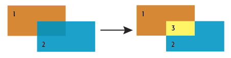
Performs an area-on-area overlay so that all input areas are intersected against each other and resultant area features are created and output. The resultant areas have all the attributes of all the original features in which they are contained.
This transformer accepts area features as input. Area features are expected to be non-self-intersecting.
Tip: If input areas are self-intersecting, first use the GeometryValidator’s Self-Intersection in 2D rule to remove self-intersections.
Area features resulting from the intersection of input areas are output through this port.
The default behavior is to use the entire set of features as the group. This option allows you to select attributes that define which groups to form.
How parallel processing works with FME: see About Parallel Processing for detailed information.
This parameter determines whether or not the transformer should perform the work across parallel processes. If it is enabled, a process will be launched for each group specified by the Group By parameter.
| Parameter | Number of Processes |
|---|---|
| No Parallelism | 1 |
| Minimal | coresThe processor, or CPU, is the physical part of the computer that performs mathematical calculations. It is the most important part of a computer system. Traditional processors have only one core on the processor, meaning that at any given time, only one set of calculations is being performed. If a processor is dual-core, this means the single chip contains hardware for two processors, now called cores to distinguish them from the single chip, running simultaneously, side by side. (Source: http://www.ehow.com/facts_5730257_computer-core-processors_.html) / 2 |
| Moderate | exact number of cores |
| Aggressive | cores x 1.5 |
| Extreme | cores x 2 |
For example, on a quad-core machine, minimal parallelism will result in two simultaneous FME processes. Extreme parallelism on an 8-core machine would result in 16 simultaneous processes.
You can experiment with this feature and view the information in the Windows Task Manager and the Workbench Log window.
The Overlap Count Attribute holds the number of features that the resultant feature overlapped, which will be at least one.
If a List Name is supplied, a list is created of all the attributes of each input area that overlaps the resultant feature.
Example:
When attributes are merged between features, existing attributes are not replaced. Therefore if the polygons being overlaid have attributes with the same name, then the values will not be transferred from one to the other. You can work around this by renaming (AttributeRenamer), prefixing (AttributeExpressionRenamer), or removing (AttributeRemover) attributes to avoid name collisions.
If the Geometry Handling Advanced setting is set to Enhanced in the workspace, ellipses accepted as areas are preserved as ellipses; otherwise, ellipses are stroked.
About Transformer Parameter Options
FME Professional edition and above
Search for samples and information about this transformer on FMEpedia.