Use this parameter to select the features that will be read:
- All Elements – All elements will be read.
- Exterior Shell Only – Only elements that belong to the exterior shell of the model will be read.
- Schedules – Features read will correspond to individual rows in Schedule tables, with one feature type for each Schedule being read. The Schedule that is read is dependent on the Specify View to Read parameter.
Use this parameter to change the geometry mode that the reader will use to represent features:
- Surfaces – This mode will represent features as 3D surfaces. Not all elements can be represented this way.
- Wireframes – This mode will represent all features as wireframes. Those that cannot be represented as surfaces will be broken down into an aggregate of lines.
- Floor Plans – This mode will represent features as a 2D floor plan. Which floor plan view is represented is dependent on the value of the Views to Read parameter.
- Area Plans – This mode will represent features as a 2D area plan. Which area plan view is represented is dependent on the value of the Views to Read parameter.
- Non-Spatial – This mode will output all features with null geometry, while still placing attributes on the correct features. This will result in a significant speed increase for the reader.
Use this parameter to decide which mode the reader should use to read floor plan views. It is only active when the Read Geometry As parameter is set to Floor Plans.
- Hidden Line – This mode will perform occlusion on features and remove those that would be hidden by others. (This is similar behavior to the “Hidden Lines” setting in the Revit program.)
- Wireframes – This mode will not perform occlusion on features. As a result, all features in the floor plan view will be output. This mode may have faster performance than Hidden Line. This is the preferred option if walls display gaps where they are intersected with plumbing and electrical features. See Autodesk Revit Troubleshooting for more information.
- GIS Mode – This mode will read the floorplan in 2D.
Use this parameter to output family instances (non-hosted only) as oriented points instead of with their regular geometry. All other feature attributes will remain unchanged.
In-place family instances that are not loadable cannot be output as family reference points.
If the Revit model contains in-place instances, the reader will output a warning and the instance’s geometry will be processed as usual.
Use this parameter to select which Revit views you wish to read from the file. The reader will read all elements from a selected view, obeying that view's visibility settings by category.
The views that you can select are dependent on the value of the Read and Read Geometry As parameters:
- If Read is set to All Elements or Exterior Shell Only, behavior depends on the Read Geometry As parameter:
- If you selected Surfaces or Wireframes, you will be able to choose from all 3D Views in the file.
- If you selected Floor Plans, you will be able to choose from all Floor Plan Views in the file.
- If no view is specified, in Surfaces or Wireframes mode, all 3D elements will be read. In Floor Plans mode, all Floor Plan Views will be read, with a string attribute applied to each feature titled FloorPlanView, containing the feature’s corresponding view.
- If Read is set to Schedules, you will be able to choose from all Schedule views in the file. If no view is selected, the reader will read one feature type for every Schedule View.
Schema Attributes
Use this parameter to expose Format Attributes in FME Workbench when you create a workspace:
- In a dynamic scenario, it means these attributes can be passed to the output dataset at runtime.
- In a non-dynamic scenario, this parameter allows you to expose additional attributes on multiple feature types. Click the browse button to view the available format attributes (which are different for each format) for the reader.
Spatial
Coordinate systems may be extracted from input feature data sources, may come predefined with FME, or may be user-defined. FME allows different output and input coordinate systems, and performs the required coordinate conversions when necessary.
If a coordinate system is specified in both the source format and the workspace, the coordinate system in the workspace is used. The coordinate system specified in the source format is not used, and a warning is logged. If a source coordinate system is not specified in the workspace and the format or system does not store coordinate system information, then the coordinate system is not set for the features that are read.
If a destination coordinate system is set and the feature has been tagged with a coordinate system, then a coordinate system conversion is performed to put the feature into the destination system. This happens right before the feature enters into the writer.
If the destination coordinate system was not set, then the features are written out in their original coordinate system.
If a destination coordinate system is set, but the source coordinate system was not specified in the workspace or stored in the source format, then no conversion is performed. The features are simply tagged with the output system name before being written to the output dataset.
For systems that know their coordinate system, the Coordinate System field will display Read from Source and FME will read the coordinate system from the source dataset. For most other input sources, the field will display Unknown (which simply means that FME will use default values). In most cases, the default value is all you'll need to perform the translation.
You can always choose to override the defaults and choose a new coordinate system. Select More Coordinate Systems from the drop-down menu to open the Coordinate System Gallery.
Changing a Reprojection
To perform a reprojection, FME typically uses the CS-MAP reprojection engine, which includes definitions for thousands of coordinate systems, with a large variety of projections, datums, ellipsoids, and units. However, GIS applications have slightly different algorithms for reprojecting data between different coordinate systems. To ensure that the data FME writes matches exactly to your existing data, you can use the reprojection engine from a different application.
To change the reprojection engine, Select Workspace Parameters > Spatial > Reprojection Engine. In the example shown, you can select Esri (but the selection here depends on your installed applications):

- The coordinate systems file coordsys.db in the FME installation folder contains the names and descriptions of all predefined coordinate systems.
- Some users may wish to use coordinate systems that do not ship with FME, and in those cases, FME also supports custom coordinate systems.
- Learn more about Working with Coordinate Systems in FME.
Use this parameter to choose the detail level that the reader will use when creating geometry for features:
- Respect Original View Setting – This mode will cause the reader to use the Detail Level setting from the view that it is currently reading.
- Fine – This mode will cause the reader to read features with a detail level of Fine.
- Medium – This mode will cause the reader to read features with a detail level of Medium.
- Coarse – This mode will cause the reader to read features with a detail level of Coarse.
- Project –
- The reader will read data in the coordinate system defined by the Revit file's Project Base Point. It will also read in the file's defined Project Units.
- Features will also be tagged with an appropriate non-earth coordinate system with the appropriate units for ease of use.
- Georeferenced –
- The reader will give precedence to an Esri product coordinate system over any native Revit coordinate system.
- If the reader cannot find an Esri coordinate system, it will read the native Revit coordinate system from the active Site in the file.
- If the reader cannot find an Esri or native Revit georeferenced coordinate system, it will read data in the coordinate system defined by the Revit file’s Survey Point. It will also read in the file’s defined Project Units.
- None –
- The reader will read data in Revit’s internal units (international feet). This mode is most useful when the data is planned to be written back to Revit with the Revit writer.
|
Esri *.prj and *.wld/wld3 Files FME will search the folder of the dataset for a file with the same name as your dataset but with a projection file (.prj) extension. If it cannot find a file with that name, it will then look for the file esri_cad.prj within the dataset folder. If either of those files exists, FME will use the coordinate system information contained within to geolocate the Revit file. If a .prj file is found, FME will also search the folder of the dataset for a file with the same name as your dataset, but with a world file extension (.wld or .wld3). If it cannot find a file with that name, it will then look for the file esri_cad.wld/esri_cad.wld3 within the dataset folder. If either of those files exists, FME will use the information in the file to translate the coordinates of the features in the dataset to their new geospatial coordinates. If no .wld/.wld3 file is found, the translation will continue using the georeferencing information found in the .prj file, while reading coordinates in the coordinate system defined by the Revit file’s Survey Point. The reader will also use the file’s defined Project Units. If the files cannot be found, then the translation will continue, using the coordinate information found in the dataset, without performing any additional transformation. For more information on creating .prj and .wld/.wld3 files in ArcGIS Pro, please refer to the ArcGIS help page: Geospatial position of CAD and BIM data. |
|
Native Revit Georeferenced Coordinate System If FME does not find an Esri .prj file, it will instead look for georeferenced coordinate system information on the active Site in the Revit dataset. In order for the dataset to be properly georeferenced, the Revit file needs to be linked to a DWG coordinate system within Autodesk Revit. If FME finds georeferencing data in the Revit dataset, it will generate a local AZMED projected coordinate system to georeference the dataset. The reader will also set the coordinate system name found in the Revit file along with the Survey Point’s latitude and longitude on the SurveyPoint feature. |
A search envelope (also known as a bounding box) is a rectangular area that defines a geographic area. In FME, the easiest way to define a search envelope is to use search envelope parameters.
Defining a search envelope is the most efficient method of selecting an area of interest because FME will read only the data that is necessary – it does not have to read an entire dataset. Search Envelope parameters apply to both vector and raster datasets and can be particularly efficient if the source format has a spatial index.
Most FME readers have parameters to define the search envelope of data that is being read:
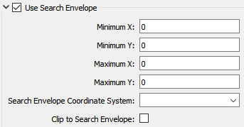
The parameters include the x and y coordinates of the bounding box as well as a parameter that defines the coordinate system.
How to Define the Bounding Box
Using the minimum and maximum x and y parameters, define a bounding box that will be used to filter the input features. Only features that intersect with the bounding box are returned. Note that the bounding box intersection is not a full geometry intersection (based on spatial relationships) that would be returned by a transformer like the SpatialFilter.
|
Search Envelope Coordinate System |
Specifies the coordinate system of the search envelope if it is different than the coordinate system of the data. The coordinate system associated with the data to be read must always be set if this parameter is set. If this parameter is set, the minimum and maximum points of the search envelope are reprojected from the Search Envelope Coordinate System to the reader’s coordinate system prior to applying the envelope. |
||||||
|
Clip to Search Envelope |
The underlying function for Use Search Envelope is an intersection; however, when Clip to Search Envelope is checked, a clipping operation is also performed.
|
Advanced
When enabled, the reader will read metadata feature types. These feature types include:
- Metadata.FamilyInformation
- Metadata.FileInformation
- Metadata.FileLinks
- Metadata.LevelInformation
- Metadata.MaterialInformation
- Metadata.ProjectPhases
- Metadata.PhaseFilters
- Metadata.PhaseGraphicOverrides
- Metadata.StyleInformation
- Metadata.ViewInformation
- Metadata.Warnings
- Metadata.Workplanes
- Metadata.Worksets
For information about these feature types, see Autodesk Revit Format Attributes (Feature Representation).
When enabled, the reader will read Sub-Component elements from Family Instances. If possible, they will be placed in the same spot on the model as they are in the family itself (for example, a pipe fitting could have Sub-Components representing each valve).
When enabled, the reader will only read built-in parameters; it will ignore any user parameters. When the reader ignores user parameters, it may help increase performance speed.
User parameters consist of Family, Project, and Shared parameters.
If enabled, the reader will read additional attributes when reading parameters. These attributes include:
-
<Param>.ParameterID – The value associated with a parameter; used to differentiate between parameters that map to the same attribute.
-
<Param>.ParameterType – The type of parameter being read (for example, Unknown, Built-In, User).
-
<Param>.Units – The units in which the parameter data is read (for example, Feet and fractional inches or Degrees). Note that this is set to empty for parameters that don’t have units, such as most string parameters.
When enabled, the reader can create a preprocessed cache to improve speed when rereading the original source data.
The cache file is stored in your default temporary folder location (for example, FME_CACHE_DIR/FME_TEMP).
More information on temporary folder location.
The cache will expire after the specified time interval, or if the original data file is modified.
The default is 14.
When set, this value represents the maximum distance between the source analytical surface and the triangle mesh.
This parameter takes any value greater than 0. The smaller the deviation, the more triangles are used.
If a value is not set, a default value of 0.05 is used.
The diagram below shows deviations when reading a circular ring.

This parameter controls reader behavior if a selected view is missing.
By default, if a view specified in the Specify View to Read parameter is missing, the reader selects the next available view.
Disabling this parameter ensures that FME logs an error if the selected view does not exist.