WCS Connection
The URL for the WCS server. A typical URL specifying a WCS server looks like:
http://www.mywcsserver.com/wcs
WCS-specific Key-Value parameters, such as Interpolation, can be passed into the source dataset URL as they would appear in the corresponding GetCoverage request.
Non-WCS-specific Key-Value parameters can appear in request URLs only when Prefer Dataset URL is checked.
This option uses the WCS source URL to build the DescribeCoverage and GetCoverage requests. It does not use the default values from the GetCapabilities result returned by the WCS server.
Choose a WFS version.
Use Network Authentication
Authentication Method
Specify the authentication method to use when accessing a password-protected server.
- Basic (default) – Basic access authentication is designed to allow a client to provide credentials to a server on the assumption that the connection between them is trusted and secure. Note that any credentials passed from client to server can be easily intercepted through an insecure connection.
- Digest – Digest authentication is one of the agreed-upon methods a web server can use to negotiate credentials, such as username or password, with a user's web browser.
- NTLM – A challenge-response protocol that is used to provide compatibility with versions of Windows earlier than the Windows 2000 operating systems.
- Web Connection – Web connections provide a convenient and secure way to store and reuse previously established connection parameters. See Web Connection below.
- Single Sign-on – FME will use the credentials of the current user to authenticate the HTTP request. This authentication method currently works only on the Windows operating system.
Web Connection
Select Coverage
Click the browse button (...) to open the Select Coverage dialog. Select a coverage and click OK.
Coverage Options
Click the browse button (...) to open the Select Format Options dialog for selecting the GetCoverage request format. Select a format and click OK.
If not specified, the reader checks if the GeoTIFF or TIFF format is supported by the server. Otherwise, the reader chooses the first format supported by FME from the list of available formats.
Click the browse button (...) to open the Select SRS Options dialog. Select a coordinate system and click OK.
If not specified, the default value is the coordinate system in which the BBOX values are expressed.
Click the browse button (...) to open the Select Datetime Options dialog. Select one or more datetime(s) and click OK.
If not specified, default BBOX values must exist on the server or must be specified in Search Envelope.
Click the browse button (...) to open the Select Interpolation Options dialog. Select an interpolation and click OK.
If not specified, the server uses the default interpolation method specified in the DescribeCoverage document.
WCS 1.0.0 requires that one of width/height/depth or RESX/RESY/RESZ is specified. The reader attempts to use default width/height/depth values from the server if neither option is checked.
- Width – The requested grid is bounded by the specified width.
- Height – The requested grid is bounded by the specified height.
- Depth – The requested grid is bounded by the specified depth.
WCS 1.0.0 requires that one of width/height/depth or RESX/RESY/RESZ is specified. The reader attempts to use default width/height/depth values from the server if neither option is checked. If Use Resolution is checked but no values for RESX/RESY/RESZ are provided, the reader attempts to retrieve the default resolution values from the server.
- Resolution X – The requested grid will be bounded by the specified x value.
- Resolution Y – The requested grid will be bounded by the specified y value.
- Resolution Z – The requested grid will be bounded by the specified z value.
Schema Attributes
Use this parameter to expose Format Attributes in FME Workbench when you create a workspace:
- In a dynamic scenario, it means these attributes can be passed to the output dataset at runtime.
- In a non-dynamic scenario, this parameter allows you to expose additional attributes on multiple feature types. Click the browse button to view the available format attributes (which are different for each format) for the reader.
Spatial
Coordinate systems may be extracted from input feature data sources, may come predefined with FME, or may be user-defined. FME allows different output and input coordinate systems, and performs the required coordinate conversions when necessary.
If a coordinate system is specified in both the source format and the workspace, the coordinate system in the workspace is used. The coordinate system specified in the source format is not used, and a warning is logged. If a source coordinate system is not specified in the workspace and the format or system does not store coordinate system information, then the coordinate system is not set for the features that are read.
If a destination coordinate system is set and the feature has been tagged with a coordinate system, then a coordinate system conversion is performed to put the feature into the destination system. This happens right before the feature enters into the writer.
If the destination coordinate system was not set, then the features are written out in their original coordinate system.
If a destination coordinate system is set, but the source coordinate system was not specified in the workspace or stored in the source format, then no conversion is performed. The features are simply tagged with the output system name before being written to the output dataset.
For systems that know their coordinate system, the Coordinate System field will display Read from Source and FME will read the coordinate system from the source dataset. For most other input sources, the field will display Unknown (which simply means that FME will use default values). In most cases, the default value is all you'll need to perform the translation.
You can always choose to override the defaults and choose a new coordinate system. Select More Coordinate Systems from the drop-down menu to open the Coordinate System Gallery.
Changing a Reprojection
To perform a reprojection, FME typically uses the CS-MAP reprojection engine, which includes definitions for thousands of coordinate systems, with a large variety of projections, datums, ellipsoids, and units. However, GIS applications have slightly different algorithms for reprojecting data between different coordinate systems. To ensure that the data FME writes matches exactly to your existing data, you can use the reprojection engine from a different application.
To change the reprojection engine, Select Workspace Parameters > Spatial > Reprojection Engine. In the example shown, you can select Esri (but the selection here depends on your installed applications):

- The coordinate systems file coordsys.db in the FME installation folder contains the names and descriptions of all predefined coordinate systems.
- Some users may wish to use coordinate systems that do not ship with FME, and in those cases, FME also supports custom coordinate systems.
- Learn more about Working with Coordinate Systems in FME.
WCS 1.1 uses GridCRSs. Each GridCRS specifies the origin and offset between recorded coverage pixels in the referenced GridBaseCRS. Since the use of GridCRS is optional, all GridCRS parameters are omitted if Use GridCRS is unchecked. If Use GridCRS is checked, all GridCRS parameters are used . Specific GridCRS parameters can be specified by passing the key-value pair in the dataset URL.
- Grid Base CRS – Reference to the CRS system of the desired output GridCRS, a URN.
- Grid Type – Reference to the Grid Type of desired output GridCRS, a URN. The default Grid Type is urn:ogc:def:method:WCS:1.1:2dSimpleGrid.
- Grid CS – Reference to the Grid CS of desired output GridCRS, a URN. The default Grid Type is urn:ogc:def:cs:OGC:0.0:Grid2dSquareCS.
- Grid Origin X – The X position coordinate of one possible grid origin, in the GridBaseCRS of desired output GridCRS.
- Grid Origin Y – The Y position coordinate of one possible grid origin, in the GridBaseCRS of desired output GridCRS.
- Grid Offset Max X – The max offset on the X axis between adjacent grid points, in GridBaseCRS of desired output GridCRS.
- Grid Offset Max Y – The max offset on the Y axis between adjacent grid points, in GridBaseCRS of desired output GridCRS.
- Grid Offset Min X – The min offset on the X axis between adjacent grid points, in GridBaseCRS of desired output GridCRS.
- Grid Offset Min Y – The min offset on the Y axis between adjacent grid points, in GridBaseCRS of desired output GridCRS.
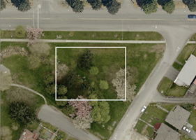
A search envelope (also known as a bounding box) is a rectangular area that defines a geographic area. In FME, the easiest way to define a search envelope is to use search envelope parameters.
Defining a search envelope is the most efficient method of selecting an area of interest because FME will read only the data that is necessary – it does not have to read an entire dataset. Search Envelope parameters apply to both vector and raster datasets and can be particularly efficient if the source format has a spatial index.
Most FME readers have parameters to define the search envelope of data that is being read:
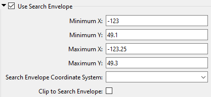
The parameters include the x and y coordinates of the bounding box as well as a parameter that defines the coordinate system.
How to Define the Bounding Box
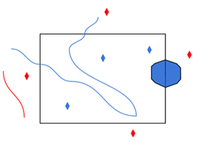
Using the minimum and maximum x and y parameters, define a bounding box that will be used to filter the input features. Only features that intersect with the bounding box are returned. Note that the bounding box intersection is not a full geometry intersection (based on spatial relationships) that would be returned by a transformer like the SpatialFilter.
|
Search Envelope Coordinate System |
Specifies the coordinate system of the search envelope if it is different than the coordinate system of the data. The coordinate system associated with the data to be read must always be set if this parameter is set. If this parameter is set, the minimum and maximum points of the search envelope are reprojected from the Search Envelope Coordinate System to the reader’s coordinate system prior to applying the envelope. |
||||||
|
Clip to Search Envelope |
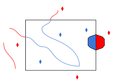
The underlying function for Use Search Envelope is an intersection; however, when Clip to Search Envelope is checked, a clipping operation is also performed.
|