By default, the reader auto-detects which version of the IFC standard is used by the source dataset. When auto-detection fails, this parameter can be used to force the reader to assume that the source data is in a particular version of the standard.
This parameter specifies whether IFC objects should be read in a relational or hierarchical manner. Because the value of this parameter affects the reader schema, this parameter can only be set when an IFC reader is added to a workspace.
By default, the IFC reader operates in Relational mode. When operating in relational mode, the IFC reader will produce a feature for each object in the IFC file. It is possible to re-create the object hierarchy using attribute values. For example, the ifc_parent_id attribute will contain the same value as the GlobalId value of the object's parent.
When operating in Hierarchical mode, the IFC reader will produce a single IfcProject feature. This feature will contain many levels of nested aggregate geometries, representing the hierarchy of objects in the source IFC file. For example, the project may contain an IFMEAggregate geometry representing an IfcSite object, which may in turn contain an IFMEAggregate representing an IfcBuilding object, and so on. Each IFC object can be identified by its geometry name. This single large feature can then be manipulated in FME Workbench, using transformers such as the GeometryPartRemover and/or the GeometryPartExtractor.
Each object in an IFC file may have multiple geometric representations, each identified with a unique name, such as Body or Axis. These parameters allow you to select whether all representations should be read.
Setting this parameter to No enables the Representations to Read/Additional Representations to Read parameters.
Each object in an IFC file may have multiple geometric representations, each identified with a unique name, such as Body or Axis. When Read all Geometric Representations is set to No, these parameters allow you to select the representations that the reader should look at.
The Representations to Read parameter provides a list of representations commonly found in IFC files. This list is taken from the IFC specification.
If a file contains representations that are not found in the list, they can be entered as a space-separated list in the Additional Representations to Read parameter.
Each geometric representation will become a part of the IFC object’s IFMEAggregate geometry. The representation identifier will be saved as the geometry name.
Property/Quantity Set Parameters
While each IFC object has a fixed schema, they may be extended the property and quantity sets.
When this parameter is set to Yes, the IFC reader will produce features that contain schema information about the names, types, and data types of these additional properties. This is useful mainly for workspaces which contain both an IFC reader and an IFC writer, as it allows the property/quantity set schema information to be preserved in the output file.
This parameter specifies the manner in which the IFC reader will handle property and quantity sets.
- Do Not Read Property/Quantity Sets – All property and quantity sets will be ignored. This can improve reader performance when property and quantity information is not required
- Geometries – Each property/quantity set will be read into the shared object library. Then, each IFC object to which the property set applies will contain a geometry instance which refers to the shared object. The shared objects can then be manipulated in FME Workbench using transformers
- Features – Each property/quantity set will be returned as a separate IfcPropertySet or IfcQuantitySet feature. These features will then be referred to via the ifc_property_set{} and ifc_quantity_set{} list attributes on IFC object features.
Type Object Parameters
This parameter controls how IFC "type objects" are handled by the reader.
The reader can read all type objects as "IfcTypeObject" features, or they can be split into their actual IFC types, such as IfcWallType, IfcSlabType, etc.
This parameter controls whether or not features representing IFC objects will contain the property/quantity sets of their corresponding type object.
If set to Yes, the reader will add the property/quantity sets of the type object to the property/quantity sets of the real object. Property/quantity sets that have the same name will be merged, giving precedence to the properties/quantities of the real object.
Encoding
This parameter may be used to provide a character set encoding which the IFC reader will use to read strings from the input file.
The IFC specification assumes that most string data is encoded in the ISO-8859-1 (Latin1) character set. In addition, the specification provides detailed information on how international characters are to be encoded in an IFC file. The IFC reader follows these specifications, and for a file that is correctly encoded, this reader parameter is not required. However, some files are produced incorrectly, and the text data in an IFC file may simply be the bytes of a string encoded in a character set other than ISO-8859-1.
Setting this reader parameter to the name of a character set allows the IFC reader to read files with incorrectly encoded international characters.
Schema Attributes
Use this parameter to expose Format Attributes in FME Workbench when you create a workspace:
- In a dynamic scenario, it means these attributes can be passed to the output dataset at runtime.
- In a non-dynamic scenario, this parameter allows you to expose additional attributes on multiple feature types. Click the browse button to view the available format attributes (which are different for each format) for the reader.
Spatial
Coordinate systems may be extracted from input feature data sources, may come predefined with FME, or may be user-defined. FME allows different output and input coordinate systems, and performs the required coordinate conversions when necessary.
If a coordinate system is specified in both the source format and the workspace, the coordinate system in the workspace is used. The coordinate system specified in the source format is not used, and a warning is logged. If a source coordinate system is not specified in the workspace and the format or system does not store coordinate system information, then the coordinate system is not set for the features that are read.
If a destination coordinate system is set and the feature has been tagged with a coordinate system, then a coordinate system conversion is performed to put the feature into the destination system. This happens right before the feature enters into the writer.
If the destination coordinate system was not set, then the features are written out in their original coordinate system.
If a destination coordinate system is set, but the source coordinate system was not specified in the workspace or stored in the source format, then no conversion is performed. The features are simply tagged with the output system name before being written to the output dataset.
For systems that know their coordinate system, the Coordinate System field will display Read from Source and FME will read the coordinate system from the source dataset. For most other input sources, the field will display Unknown (which simply means that FME will use default values). In most cases, the default value is all you'll need to perform the translation.
You can always choose to override the defaults and choose a new coordinate system. Select More Coordinate Systems from the drop-down menu to open the Coordinate System Gallery.
Changing a Reprojection
To perform a reprojection, FME typically uses the CS-MAP reprojection engine, which includes definitions for thousands of coordinate systems, with a large variety of projections, datums, ellipsoids, and units. However, GIS applications have slightly different algorithms for reprojecting data between different coordinate systems. To ensure that the data FME writes matches exactly to your existing data, you can use the reprojection engine from a different application.
To change the reprojection engine, Select Workspace Parameters > Spatial > Reprojection Engine. In the example shown, you can select Esri (but the selection here depends on your installed applications):

- The coordinate systems file coordsys.db in the FME installation folder contains the names and descriptions of all predefined coordinate systems.
- Some users may wish to use coordinate systems that do not ship with FME, and in those cases, FME also supports custom coordinate systems.
- Learn more about Working with Coordinate Systems in FME.
Geometry
This parameter specifies whether the reader will preserve or remove the geometric representations of IfcSpace features. IfcSpace geometries are virtual areas or volumes that provide for certain functions within a building. As such, the geometries do not represent actual physical objects. When physical entities are most important, preserving these volumes of space may not be desirable.
- Yes – IfcSpace features will contain the geometric representations of the space.
- No (default) – IfcSpace features will not contain geometric representations.
This parameter specifies whether the geometric representations of openings should be subtracted from the geometric representations of the objects they are related to. In practical terms, the parameter specifies whether window openings should be cut out of walls, or fastener holes cut out of beam features.
- Yes (default): The openings will be cut out of their parent feature geometry, and the opening features will have no geometric representation.
- No: The openings will not be cut out of their parent geometry. Instead the opening features will contain the geometric representations. This allows the subtraction to be performed later, using the CSGBuilder transformer in FME Workbench.
This parameter specifies whether the geometric representations of projecting elements (for example, pilasters and other decorative items) should be added to the geometric representations of the objects they are related to. This will apply to any object whose type is a subtype of IfcFeatureElementAddition.
- Yes (default) – The projecting geometries will be added to their parent feature geometry using a CSG union operation. The projection features will have no geometric representation.
- No – The projecting geometries will not be added to their parent geometry. Instead, the projection features will contain the geometric representations. This allows the addition to be performed later, using the CSGBuilder transformer in FME Workbench.
This parameter specifies whether or not the reader should evaluate CSG solid geometries. If the CSG evaluation is not performed in the IFC reader, FME will automatically perform the evaluation when it is required. However, in some cases, this will result in solids which contain extraneous faces or protrusions. This can be prevented by having the IFC reader evaluate all CSG solids as they are read.
The default value for this parameter is No.
In IFC, some geometries can be specified with curved corners. This is particularly common for structural beams which have a C, I, L, T, U, or Z-shaped profile, or a rounded rectangular profile. These curved corners can dramatically increase the number of faces in a solid. If the solid is involved in a CSG subtraction, the extra faces will significantly slow down the CSG evaluation. The extra faces can be avoided by setting this parameter to Yes. In this case, the rounded corners will be replaced with 90 degree corners.
The default value for this parameter is No.
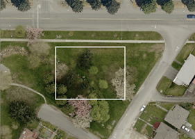
A search envelope (also known as a bounding box) is a rectangular area that defines a geographic area. In FME, the easiest way to define a search envelope is to use search envelope parameters.
Defining a search envelope is the most efficient method of selecting an area of interest because FME will read only the data that is necessary – it does not have to read an entire dataset. Search Envelope parameters apply to both vector and raster datasets and can be particularly efficient if the source format has a spatial index.
Most FME readers have parameters to define the search envelope of data that is being read:
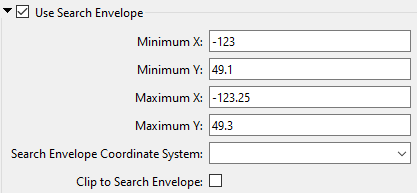
The parameters include the x and y coordinates of the bounding box as well as a parameter that defines the coordinate system.
How to Define the Bounding Box
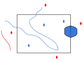
Using the minimum and maximum x and y parameters, define a bounding box that will be used to filter the input features. Only features that intersect with the bounding box are returned. Note that the bounding box intersection is not a full geometry intersection (based on spatial relationships) that would be returned by a transformer like the SpatialFilter.
|
Search Envelope Coordinate System |
Specifies the coordinate system of the search envelope if it is different than the coordinate system of the data. The coordinate system associated with the data to be read must always be set if this parameter is set. If this parameter is set, the minimum and maximum points of the search envelope are reprojected from the Search Envelope Coordinate System to the reader’s coordinate system prior to applying the envelope. |
||||||
|
Clip to Search Envelope |
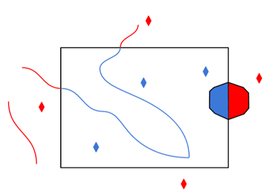
The underlying function for Use Search Envelope is an intersection; however, when Clip to Search Envelope is checked, a clipping operation is also performed.
|