|
Database formats include a Database Connection parameter that defines and stores authentication information. For general information about sharing database connections, please see Using Database Connections. Note that Database Connection parameters differ slightly, depending on context and/or database format. |
|
Connection From the Connection parameter in a database format, you can do one of the following:
|
Database Connection
Select an existing Esri Knowledge Graph connection, or Add Database Connection...
|
Add Esri Knowledge Server Connection To define a new connection from the Connection parameter, see the topic Esri Knowledge: Add Connection. |
Constraints
After specifying the database connection, click the Browse button (...) to select tables for import. A connection window appears while the system retrieves the tables from the database.
Once the Select Tables dialog appears, you can select one or more tables. Click OK to dismiss the window and add the selected table name(s) to the Tables parameter.
The WHERE clause parameter is used to constrain the row selection in tables chosen in the Tables parameter. FME will select only the rows (records) that match this condition.
The easiest method to construct a WHERE clause is by using the editor. Click the browse button (...) to open the editor, and use the SQL functions to construct the clause.
You can also type a WHERE clause directly in the parameter field:
|
Examples |
|---|
|
When querying integer and number data types: NUMLANES = 2 LENGTH > 2000 |
If the WHERE clause SQL is invalid, the translation will fail.
 in the WHERE Clause editor.
Check this box to exclude non-spatial tables, relationships, and domains from a translation.
If this option is enabled when generating a workspace, then schemas will not be returned for non-spatial tables.
Check this box to resolve the domain code found in feature classes and tables into the domain value.
This means that when an attribute of a feature has a coded value domain associated with it, another attribute will also be added that represents the textual description of the coded attribute.
The new attribute will be <attribute-name>_resolved, where <attribute-name> is the name of the attribute containing the code.
Schema Attributes
Use this parameter to expose Format Attributes in FME Workbench when you create a workspace:
- In a dynamic scenario, it means these attributes can be passed to the output dataset at runtime.
- In a non-dynamic scenario, this parameter allows you to expose additional attributes on multiple feature types. Click the browse button to view the available format attributes (which are different for each format) for the reader.
This parameter controls how Knowledge Graph aliases are used.
None – Aliases are ignored.
Replace Attribute Names with Aliases – (only applicable when adding a Reader) Attributes on feature types will be named for their aliases rather than their official names. A kg_entity_alias attribute will be included on each feature. Use this mode when the target format should create feature types using the aliases as attribute names.
Expose Aliases as Metadata Attributes – For each attribute read, a second <name>_alias attribute will be added that stores the alias for the attribute in question. A kg_entity_alias attribute will also be included on each feature. Use this mode when the target format is Esri Knowledge and the aliases should be preserved during feature class and table creation.
Spatial
Coordinate systems may be extracted from input feature data sources, may come predefined with FME, or may be user-defined. FME allows different output and input coordinate systems, and performs the required coordinate conversions when necessary.
If a coordinate system is specified in both the source format and the workspace, the coordinate system in the workspace is used. The coordinate system specified in the source format is not used, and a warning is logged. If a source coordinate system is not specified in the workspace and the format or system does not store coordinate system information, then the coordinate system is not set for the features that are read.
If a destination coordinate system is set and the feature has been tagged with a coordinate system, then a coordinate system conversion is performed to put the feature into the destination system. This happens right before the feature enters into the writer.
If the destination coordinate system was not set, then the features are written out in their original coordinate system.
If a destination coordinate system is set, but the source coordinate system was not specified in the workspace or stored in the source format, then no conversion is performed. The features are simply tagged with the output system name before being written to the output dataset.
For systems that know their coordinate system, the Coordinate System field will display Read from Source and FME will read the coordinate system from the source dataset. For most other input sources, the field will display Unknown (which simply means that FME will use default values). In most cases, the default value is all you'll need to perform the translation.
You can always choose to override the defaults and choose a new coordinate system. Select More Coordinate Systems from the drop-down menu to open the Coordinate System Gallery.
Changing a Reprojection
To perform a reprojection, FME typically uses the CS-MAP reprojection engine, which includes definitions for thousands of coordinate systems, with a large variety of projections, datums, ellipsoids, and units. However, GIS applications have slightly different algorithms for reprojecting data between different coordinate systems. To ensure that the data FME writes matches exactly to your existing data, you can use the reprojection engine from a different application.
To change the reprojection engine, Select Workspace Parameters > Spatial > Reprojection Engine. In the example shown, you can select Esri (but the selection here depends on your installed applications):

- The coordinate systems file coordsys.db in the FME installation folder contains the names and descriptions of all predefined coordinate systems.
- Some users may wish to use coordinate systems that do not ship with FME, and in those cases, FME also supports custom coordinate systems.
- Learn more about Working with Coordinate Systems in FME.
Search Envelope
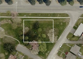
A search envelope (also known as a bounding box) is a rectangular area that defines a geographic area. In FME, the easiest way to define a search envelope is to use search envelope parameters.
Defining a search envelope is the most efficient method of selecting an area of interest because FME will read only the data that is necessary – it does not have to read an entire dataset. Search Envelope parameters apply to both vector and raster datasets and can be particularly efficient if the source format has a spatial index.
Most FME readers have parameters to define the search envelope of data that is being read:
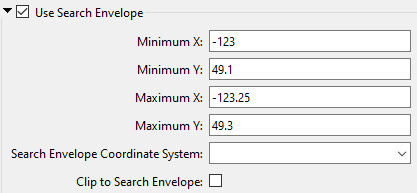
The parameters include the x and y coordinates of the bounding box as well as a parameter that defines the coordinate system.
How to Define the Bounding Box
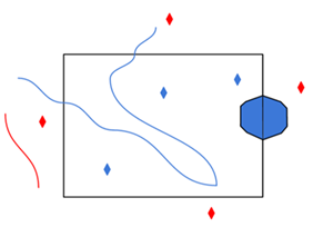
Using the minimum and maximum x and y parameters, define a bounding box that will be used to filter the input features. Only features that intersect with the bounding box are returned. Note that the bounding box intersection is not a full geometry intersection (based on spatial relationships) that would be returned by a transformer like the SpatialFilter.
|
Search Envelope Coordinate System |
Specifies the coordinate system of the search envelope if it is different than the coordinate system of the data. The coordinate system associated with the data to be read must always be set if this parameter is set. If this parameter is set, the minimum and maximum points of the search envelope are reprojected from the Search Envelope Coordinate System to the reader’s coordinate system prior to applying the envelope. |
||||||
|
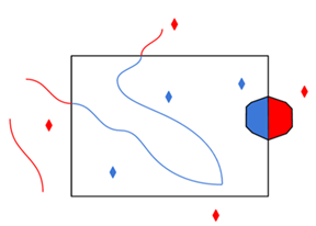
Clip to Search Envelope |
The underlying function for Use Search Envelope is an intersection; however, when Clip to Search Envelope is checked, a clipping operation is also performed.
|
Specifies the order that the underlying search is performed:
- Spatial First – Perform spatial query first.
- Attribute First – Perform tabular query first (when performing a WHERE clause search).
Advanced
In some programs (for example, ArcGIS Pro), GlobalID and GUID attributes contain braces:
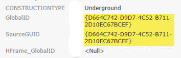
When set to Yes, this parameter removes the braces from the GlobalID and GUID attributes for compatibility with programs where these attributes do not contain braces.
The default is No.
Specifies whether to create a connection that persists and can be shared by other readers, writers, and transformers.
When set to Yes, the connection will remain open until FME shuts down, even if this reader is finished using it. Otherwise, the connection will be closed when the reader is shut down (unless another reader, writer, or transformer is still using the connection).
Creating a new connection is a resource-expensive operation. Depending on how FME is being used (for example, if there are multiple instances of the reader/writer being used), performance may improve by setting this parameter to Yes.