FME Transformers: 2025.0
Creates a buffer zone of specified size around or inside input geometry.
Typical Uses
- Creating fixed size zones around features, such as rights-of-way or setbacks
- Determining spatial relationships based on proximity
- Creating variable size zones around features to represent attribute values
How does it work?
The Bufferer accepts 2D point, curve (line), and area geometries when the Buffer Type is Area (2D). All geometry types are accepted when the Buffer Type is Solid.
Points and curves may be expanded, creating surrounding polygons or solids with points offset by the specified Buffer Distance in the specified units. Areas may be expanded or shrunk, using positive or negative Buffer Distances, but solids require positive Buffer Distances.
The attributes of the original features are retained, and the buffer is output, discarding the original geometry.
A selection of end cap and corner styles is available.
An optional list attribute may be created, holding multiple attributes for grouped or aggregate input.
Examples
In this example, we buffer arterial streets (shown in blue) to find address points that fall within a fixed distance of them. The streets data is in a UTM coordinate system, with ground units in meters.
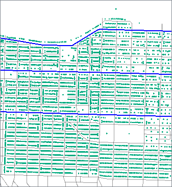
The arteries are routed into a Bufferer.

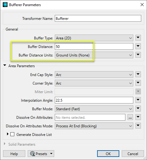
We enter a Buffer Distance of 50, and leave the Buffer Distance Units as the default setting Ground Units (None). This will produce buffers of 50 meters to either side of the street.
The Buffer Type is the default, Area (2D) .
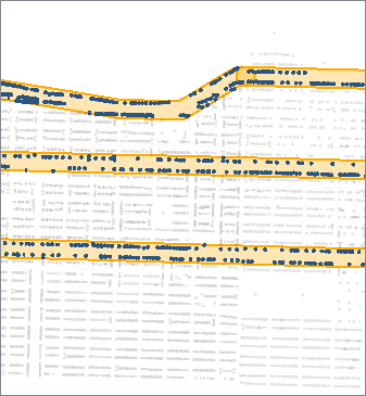
The buffered streets are then sent to a SpatialFilter, along with the address points, and are tested for points that fall within the buffers.
In this example, we create buffer zones around rapid transit lines. The source data is KML, in a geographic lat/long projection.
As the ground units are in degrees, the data must be reprojected before making calculations in units like meters or feet. The Buffer Distance Units parameter will take care of that.
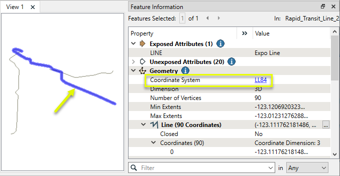
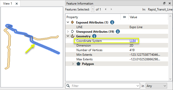
The lines are routed into a Bufferer.

In the parameters dialog, we select Meters as our ground unit of choice, and set a Buffer Distance of 150.

The resulting Output buffer polygons retain the attributes of the original features, and are projected in the original lat/long coordinate system.
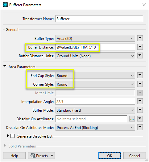
In this example, we take a point dataset of food carts that has an attribute containing the average number of daily customers they serve. We route the points into the Bufferer.

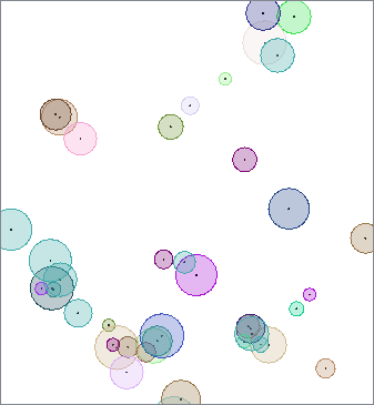
A bit of experimentation shows that dividing the daily traffic numbers by 10 will produce a desirable range of bubble sizes, and so we set the Buffer Distance to the value of the DAILY_TRAF attribute, divided by 10.
The resulting buffers are colored according to the category of food cart (type of food served).
Usage Notes
- This transformer creates buffers that are of equal width on either side of a linear input feature. To create offsets to either the left or right-hand side of a feature, use the OffsetCurveGenerator.
- Areas will be buffered on one side only - externally for a positive Buffer Distance, and internally for a negative Buffer Distance.
- Output area buffers will always have a Right Hand Rule orientation.
- This transformer may produce unexpected results when input areas are self-intersecting or when input lines double back on themselves. A GeometryFilter may be used to identify invalid geometries produced in these cases.
Configuration
Input Ports
If the Buffer Type parameter is Area (2D), then only 2D geometries are accepted as input.
If the Buffer Type parameter is Solid, then all geometry types are accepted as input.
Output Ports
An area or solid representing the region that is within the specified buffer distance of the input geometry. A null geometry is output if this region would be empty.
The original geometry is not output.
Features with invalid geometries are output through this port along with an additional attribute, fme_rejection_code, to indicate the reason for rejection.
If the Buffer Type parameter is Solid, negative buffer distance will cause a feature to be rejected.
If the Buffer Type parameter is Area (2D) non-2D geometries will be rejected.
If the Buffer Distance Units parameter is set to anything other than Ground Units (None), features without coordinate systems will be rejected.
Rejected Feature Handling: can be set to either terminate the translation or continue running when it encounters a rejected feature. This setting is available both as a default FME option and as a workspace parameter.
Parameters
|
Buffer Type |
Specify whether to create Area (2D) or Solid buffers around input features. |
|
Buffer Distance |
Each point on the boundary of the output area or solid is the specified amount, measured in the specified units, away from the input geometry.
Note that a Buffer Distance of 0 will produce:
|
|
Buffer Distance Units |
When Buffer Type is Area (2D), the units of the Buffer Distance may be specified as something other than ground units. This setting is designed for use with features in any valid coordinate system (geographic or other), and so may be used to create flexible workspaces that can buffer regardless of input coordinate systems and units. If a specific unit is chosen, it may reproject input features into the Dynamic Equal Distance projection, buffer them, then reproject them back into the original coordinate system. Input features without a coordinate system defined will be output via the Rejected port. |
These parameters are only enabled when the Buffer Type is Area (2D).
|
End Cap Style |
When buffering a point or curve, you can select an end-cap style. Choices include:
|
||||||||||||
|
Corner Style |
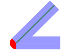
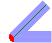
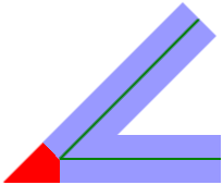
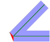
When buffering a curve or area, you can select a corner style. Choices include:
|
||||||||||||
|
Miter Limit |
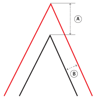
Miter Limit This parameter controls how pointed a buffered corner can be before it is beveled. It is the highest value that the ratio of corner distance to offset is allowed to have before truncation occurs. A higher number allows for more extreme corner angles.
Miter Ratio = Corner distance / Offset
|
||||||||||||
|
Interpolation Angle |
Used for the Round End Cap Style and the Round Corner Style. It controls the smoothness of the interpolated lines in the output buffer boundaries, specifying what angles should be used to approximate the circular corner. As this parameter decreases in value, the smoothness of the interpolated corners increases. The value is specified in degrees and must be greater than 0 and less than or equal to 90. |
||||||||||||
|
Buffer Mode |
Controls whether input geometries are simplified before buffering.
|
||||||||||||
|
Dissolve On Attributes |
Allows dissolving groups of buffered features with common values for the specified attributes. By default, no dissolving of buffered features takes place. |
||||||||||||
|
Dissolve On Attributes Mode |
Process At End (Blocking): This is the default behavior. Processing will only occur in this transformer once all input is present. Process When Dissolve Attributes Change (Advanced): This transformer will process input groups in order. Changes of the value of the Dissolve On Attributes parameter on the input stream will trigger processing on the currently accumulating group. This may improve overall speed (particularly with multiple, equally-sized groups), but could cause undesired behavior if input groups are not truly ordered. There are two typical reasons for using Process When Dissolve Attributes Change (Advanced) . The first is incoming data that is intended to be processed in groups (and is already so ordered). In this case, the structure dictates Dissolve On Attributes usage - not performance considerations. The second possible reason is potential performance gains. Performance gains are most likely when the data is already sorted (or read using a SQL ORDER BY statement) since less work is required of FME. If the data needs ordering, it can be sorted in the workspace (though the added processing overhead may negate any gains). Sorting becomes more difficult according to the number of data streams. Multiple streams of data could be almost impossible to sort into the correct order, since all features matching a Dissolve On Attributes value need to arrive before any features (of any feature type or dataset) belonging to the next group. In this case, using Dissolve On Attributes with Process At End (Blocking) may be the equivalent and simpler approach. Note Multiple feature types and features from multiple datasets will not generally naturally occur in the correct order.
As with many scenarios, testing different approaches in your workspace with your data is the only definitive way to identify performance gains. |
When enabled, adds a list attribute to the Buffered output features. This parameter is useful when using Dissolve On Attributes or if input features contain aggregates. Within each group or aggregate, within each dissolved region, attributes from an input feature with the largest area are stored at the head of the list, and no order is defined for the remaining elements.
|
List Name |
Enter a name for the list attribute. Note List attributes are not accessible from the output schema in FME Workbench unless they are first processed using a transformer that operates on them, such as ListExploder or ListConcatenator. Alternatively, AttributeExposer can be used.
|
|
Add To List |
All Attributes: All attributes will be added to the output features. Selected Attributes: Enables the Selected Attributes parameter, where specific attributes may be chosen for inclusion. |
|
Selected Attributes |
Enabled when Add To List is set to Selected Attributes. Specify the attributes you wish to be included. |
This parameter is only enabled when the Buffer Type is Solid.
|
Edge Resolution |
A round buffer is generated along all edges and corners for the solid. An approximation of a sphere is used to build up these edges. This resolution parameter determines the level of subdivision to use for this sphere. The sphere is generated using the quadrilateralized spherical cube mapping so the final sphere will consist of 6n^2 faces, for a value of n. The value must be an integer greater than 1. This buffer solid produces a better approximation of a uniform buffer distance with higher levels of subdivision, at the cost of performance of the buffer operations. |
Editing Transformer Parameters
Transformer parameters can be set by directly entering values, using expressions, or referencing other elements in the workspace such as attribute values or user parameters. Various editors and context menus are available to assist. To see what is available, click  beside the applicable parameter.
Defining Values
There are several ways to define a value for use in a Transformer. The simplest is to simply type in a value or string, which can include functions of various types such as attribute references, math and string functions, and workspace parameters.
Using the Text Editor
The Text Editor provides a convenient way to construct text strings (including regular expressions) from various data sources, such as attributes, parameters, and constants, where the result is used directly inside a parameter.
Using the Arithmetic Editor
The Arithmetic Editor provides a convenient way to construct math expressions from various data sources, such as attributes, parameters, and feature functions, where the result is used directly inside a parameter.
Conditional Values
Set values depending on one or more test conditions that either pass or fail.
Parameter Condition Definition Dialog
Content
Expressions and strings can include a number of functions, characters, parameters, and more.
When setting values - whether entered directly in a parameter or constructed using one of the editors - strings and expressions containing String, Math, Date/Time or FME Feature Functions will have those functions evaluated. Therefore, the names of these functions (in the form @<function_name>) should not be used as literal string values.
| These functions manipulate and format strings. | |
|
Special Characters |
A set of control characters is available in the Text Editor. |
| Math functions are available in both editors. | |
| Date/Time Functions | Date and time functions are available in the Text Editor. |
| These operators are available in the Arithmetic Editor. | |
| These return primarily feature-specific values. | |
| FME and workspace-specific parameters may be used. | |
| Creating and Modifying User Parameters | Create your own editable parameters. |
Table Tools
Transformers with table-style parameters have additional tools for populating and manipulating values.
|
Row Reordering
|
Enabled once you have clicked on a row item. Choices include:
|
|
Cut, Copy, and Paste
|
Enabled once you have clicked on a row item. Choices include:
Cut, copy, and paste may be used within a transformer, or between transformers. |
|
Filter
|
Start typing a string, and the matrix will only display rows matching those characters. Searches all columns. This only affects the display of attributes within the transformer - it does not alter which attributes are output. |
|
Import
|
Import populates the table with a set of new attributes read from a dataset. Specific application varies between transformers. |
|
Reset/Refresh
|
Generally resets the table to its initial state, and may provide additional options to remove invalid entries. Behavior varies between transformers. |
Note: Not all tools are available in all transformers.
For more information, see Transformer Parameter Menu Options.
Reference
|
Processing Behavior |
Dependent on Dissolve On Attributes parameter. If:
|
|
Feature Holding |
Dependent on Dissolve On Attributes parameter. If:
|
| Dependencies | |
| Aliases | 3DBufferer, GeographicBufferer |
| History |
FME Community
The FME Community has a wealth of FME knowledge with over 20,000 active members worldwide. Get help with FME, share knowledge, and connect with users globally.
Search for all results about the Bufferer on the FME Community.
Examples may contain information licensed under the Open Government Licence – Vancouver, Open Government Licence - British Columbia, and/or Open Government Licence – Canada.


