FME Transformers: 2024.1
Categories
Spatial Analysis
Outputs circular sectors of influence for point features that have directions defined by azimuths (degrees clockwise from North).
This transformer creates a number of sectors for each set of point features (collectively called a site), depending on each point’s direction of influence. Each sector fans out from the center point (site point) of the site it belongs to, and has a user-defined radius.
This transformer generates a Voronoi diagram that consists of polygons representing the closest areas around center points of sectors (site points). The final output will be the sectors truncated to the extents of their site’s corresponding Voronoi polygons.
This transformer has an additional output port that produces sectors truncated by Voronoi polygons, to eliminate possible overlaps between different sites.
Note To create sectors that may overlap with sectors of other sites, use the SectorGenerator transformer instead.
Example
In the telecommunications industry, directional antennas are used in conjunction with each other for better coverage and stronger signal reception. These antennas each cover a sector of a complete circle that an antenna tower covers, with some areas of overlap between each two sectors.
This transformer can be used to determine the “Nominal” (assuming a whole circle is covered and there are no overlaps between any two sectors) coverage field of directional antennas and receivers.
Input points and their azimuth values are received:
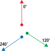
A center point is created for each site:
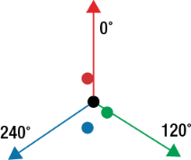
Note Please note that after this step, the locations of input points play no part in the generation of sectors, and the values that determine sectors are the input points’ azimuths and radii.
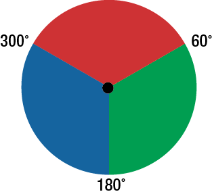
Polygon sectors are generated. The sector corresponding to each point will span an area determined by the radius set and:
(The point's azimuth + adjacent azimuth (in degrees))/2
Two sides of a sector are found by one time choosing the closest azimuth clockwise and the next time counter-clockwise. Resulting sectors will look like this:
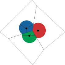
Voronoi polygons are generated, based on site points:
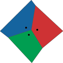
If two sites have overlapping sectors, the sectors are clipped by the Voronoi polygons to generate Cells:
Configuration
Input Ports
This transformer accepts only points. All other geometries are rejected.
If 3D points enter this transformer, they are treated as if they were 2D points.
Output Ports
Sector polygons are output unclipped via this port. Output sectors of different sites may overlap each other.
These are the Voronoi polygons produced by the transformer and used to clip the output polygons of the Cells port.
Cells are sectors truncated by Voronoi polygons. The output sectors from this port do not overlap. To ensure correct output from this port, please refer to the Radius parameter.
For each site, a point is created with coordinates that are the average of the coordinates of all points accepted for that sector. This point is the center of all sectors generated for a site.
If a Sector Name Attribute is specified and there are points with the same sector and site names, only the first point meeting all requirements is considered for creating sectors and the rest are output from this port.
Upon entering transformer, if a point is found to be farther from any of the other points in its site than the specified Maximum Distance Between Site Points, it will be dropped from sector generation and output from this port.
Invalid features are left untouched and output via this port. Invalid features are non-point features and point features with missing or invalid values for required attributes.
Parameters
|
Site Name Attribute |
This is the attribute that determines the site to which an input point belongs. |
|
Azimuth Attribute |
The direction each input point faces (or influences). The Azimuth Attribute is measured in degrees clockwise from North. Valid Azimuth Attribute values are positive and less than 360. |
|
Sector Name Attribute |
If a Sector Name Attribute is specified and there are points with the same sector name in a site, only one of the points is considered for creating sectors. Each feature entering the transformer is checked. If its sector name is already in use within its site, it will be output on the ExtraPoints port. |
|
This parameter defines the radius of influence for each sector. This determines the radius of each sector in a site. Note Values of Radii larger than the extents of the area covered by the site points will produce invalid results. Differing values of radii for overlapping sectors will also result in incorrect output.
|
|
|
This parameter specifies the maximum distance a point can be from any other point in its site and still be considered in sector creation. Points are considered in the order they enter the transformer, with each new point tested against all other points already accepted as a part of its site. If a nonconstant value is specified for this parameter (for example, an attribute value, which may differ from feature to feature), then when comparing the distance between two features, the maximum distance will be calculated from the feature that entered the transformer earlier. |
|
|
Ensure Topological Correctness |
No: There may be slight overlaps or gaps between sectors, making the output unsuitable for some geometric operations. Note that the input points should be in a way that the transformer is able to produce at least three different site points that are not collinear, since a Voronoi Diagram is generated for analysis. |
Editing Transformer Parameters
Transformer parameters can be set by directly entering values, using expressions, or referencing other elements in the workspace such as attribute values or user parameters. Various editors and context menus are available to assist. To see what is available, click  beside the applicable parameter.
Defining Values
There are several ways to define a value for use in a Transformer. The simplest is to simply type in a value or string, which can include functions of various types such as attribute references, math and string functions, and workspace parameters.
Using the Text Editor
The Text Editor provides a convenient way to construct text strings (including regular expressions) from various data sources, such as attributes, parameters, and constants, where the result is used directly inside a parameter.
Using the Arithmetic Editor
The Arithmetic Editor provides a convenient way to construct math expressions from various data sources, such as attributes, parameters, and feature functions, where the result is used directly inside a parameter.
Conditional Values
Set values depending on one or more test conditions that either pass or fail.
Parameter Condition Definition Dialog
Content
Expressions and strings can include a number of functions, characters, parameters, and more.
When setting values - whether entered directly in a parameter or constructed using one of the editors - strings and expressions containing String, Math, Date/Time or FME Feature Functions will have those functions evaluated. Therefore, the names of these functions (in the form @<function_name>) should not be used as literal string values.
| These functions manipulate and format strings. | |
|
Special Characters |
A set of control characters is available in the Text Editor. |
| Math functions are available in both editors. | |
| Date/Time Functions | Date and time functions are available in the Text Editor. |
| These operators are available in the Arithmetic Editor. | |
| These return primarily feature-specific values. | |
| FME and workspace-specific parameters may be used. | |
| Creating and Modifying User Parameters | Create your own editable parameters. |
Table Tools
Transformers with table-style parameters have additional tools for populating and manipulating values.
|
Row Reordering
|
Enabled once you have clicked on a row item. Choices include:
|
|
Cut, Copy, and Paste
|
Enabled once you have clicked on a row item. Choices include:
Cut, copy, and paste may be used within a transformer, or between transformers. |
|
Filter
|
Start typing a string, and the matrix will only display rows matching those characters. Searches all columns. This only affects the display of attributes within the transformer - it does not alter which attributes are output. |
|
Import
|
Import populates the table with a set of new attributes read from a dataset. Specific application varies between transformers. |
|
Reset/Refresh
|
Generally resets the table to its initial state, and may provide additional options to remove invalid entries. Behavior varies between transformers. |


Note: Not all tools are available in all transformers.
For more information, see Transformer Parameter Menu Options.
FME Community
The FME Community is the place for demos, how-tos, articles, FAQs, and more. Get answers to your questions, learn from other users, and suggest, vote, and comment on new features.
Search for all results about the VoronoiCellGenerator on the FME Community.