Materials
This parameter specifies the folders from which the reader will search to find the texture image files referenced by the DirectX files being read.
Spatial
Coordinate systems may be extracted from input feature data sources, may come predefined with FME, or may be user-defined. FME allows different output and input coordinate systems, and performs the required coordinate conversions when necessary.
If a coordinate system is specified in both the source format and the workspace, the coordinate system in the workspace is used. The coordinate system specified in the source format is not used, and a warning is logged. If a source coordinate system is not specified in the workspace and the format or system does not store coordinate system information, then the coordinate system is not set for the features that are read.
If a destination coordinate system is set and the feature has been tagged with a coordinate system, then a coordinate system conversion is performed to put the feature into the destination system. This happens right before the feature enters into the writer.
If the destination coordinate system was not set, then the features are written out in their original coordinate system.
If a destination coordinate system is set, but the source coordinate system was not specified in the workspace or stored in the source format, then no conversion is performed. The features are simply tagged with the output system name before being written to the output dataset.
For systems that know their coordinate system, the Coordinate System field will display Read from Source and FME will read the coordinate system from the source dataset. For most other input sources, the field will display Unknown (which simply means that FME will use default values). In most cases, the default value is all you'll need to perform the translation.
You can always choose to override the defaults and choose a new coordinate system. Select More Coordinate Systems from the drop-down menu to open the Coordinate System Gallery.
Changing a Reprojection
To perform a reprojection, FME typically uses the CS-MAP reprojection engine, which includes definitions for thousands of coordinate systems, with a large variety of projections, datums, ellipsoids, and units. However, GIS applications have slightly different algorithms for reprojecting data between different coordinate systems. To ensure that the data FME writes matches exactly to your existing data, you can use the reprojection engine from a different application.
To change the reprojection engine, Select Workspace Parameters > Spatial > Reprojection Engine. In the example shown, you can select Esri (but the selection here depends on your installed applications):

- The coordinate systems file coordsys.db in the FME installation folder contains the names and descriptions of all predefined coordinate systems.
- Some users may wish to use coordinate systems that do not ship with FME, and in those cases, FME also supports custom coordinate systems.
- Learn more about Working with Coordinate Systems in FME.
DirectX uses a left-handed coordinate system (LHCS), while FME natively uses a right-handed coordinate system (RHCS).
During import, DirectX features will be transformed to convert to a RHCS according to the option selected on the reader.
- Flip Z – FME will convert DirectX elements to RHCS by scaling all z-values by negative one (-1).
- Swap Y and Z – FME will convert DirectX elements to RHCS by swapping the Y and Z axes.
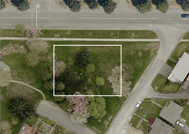
A search envelope (also known as a bounding box) is a rectangular area that defines a geographic area. In FME, the easiest way to define a search envelope is to use search envelope parameters.
Defining a search envelope is the most efficient method of selecting an area of interest because FME will read only the data that is necessary – it does not have to read an entire dataset. Search Envelope parameters apply to both vector and raster datasets and can be particularly efficient if the source format has a spatial index.
Most FME readers have parameters to define the search envelope of data that is being read:
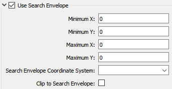
The parameters include the x and y coordinates of the bounding box as well as a parameter that defines the coordinate system.
How to Define the Bounding Box
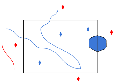
Using the minimum and maximum x and y parameters, define a bounding box that will be used to filter the input features. Only features that intersect with the bounding box are returned. Note that the bounding box intersection is not a full geometry intersection (based on spatial relationships) that would be returned by a transformer like the SpatialFilter.
|
Search Envelope Coordinate System |
Specifies the coordinate system of the search envelope if it is different than the coordinate system of the data. The coordinate system associated with the data to be read must always be set if this parameter is set. If this parameter is set, the minimum and maximum points of the search envelope are reprojected from the Search Envelope Coordinate System to the reader’s coordinate system prior to applying the envelope. |
||||||
|
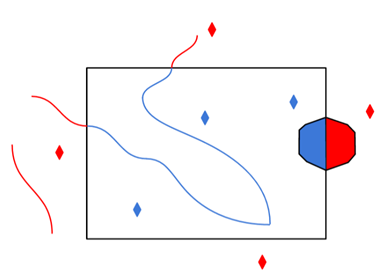
Clip to Search Envelope |
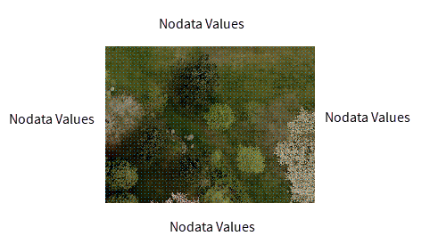
The underlying function for Use Search Envelope is an intersection; however, when Clip to Search Envelope is checked, a clipping operation is also performed.
|