Creates features using the parameters supplied, and sends them into the workspace for processing.
The Creator's interface allows you to select the desired type of geometry, then enter the coordinates and/or parameters that will create the desired object.
Input Ports
This transformer does not have any input ports.
Output Ports
All created features are output through this port.
Parameters
This parameter specifies how to create the geometry, using the options listed below. Your choice for this parameter determines whether other parameters are enabled or disabled.
- Geometry Object: This option allows you to create the geometry types specified in the Geometry Object parameter below. The XML tab shows, by default, the XML representation of any object defined in the other areas of the dialog.
- 2D Coordinate List:Creates two-dimensional geometry from the space-delimited list of x y coordinates entered in the Coordinate List parameter field.
- 3D Coordinate List: Creates two-dimensional geometry with z-values from the space-delimited list of x y z coordinates entered in the Coordinate List parameter field.
- 2D Min/Max Box: Creates a bounding box from bottom left and top right corner, specified as minx miny maxx maxy in the Coordinate List parameter field (for example: 0 0 10 10).
| Geometry Object | Description | |||||||||||||||||||||
|---|---|---|---|---|---|---|---|---|---|---|---|---|---|---|---|---|---|---|---|---|---|---|
|
Null |
Creates an object without geometry. For some applications, it can be useful to have such an object available; for example, when you are using a CSV writer but you want to output a header or footer. | |||||||||||||||||||||
|
Point |
Creates a single point at the given coordinates. | |||||||||||||||||||||
|
Text |
Creates a single text object at the given coordinates, using the text string, height and rotation. | |||||||||||||||||||||
|
Line |
Creates a single line object using the specified coordinate pairs. If you want to create an area, use the Polygon option instead. Even if you specify the first and last coordinate pairs to be the same, the type of the object generated will still be fme_line. |
|||||||||||||||||||||
|
Arc by center point/ |
Arc by center point creates an arc using the specified parameters. Arc by center point with ends: All fields are required (including start and sweep angles), except rotation. The three coordinates given must match the arcs (sweep and start angles) or else the Creator will produce an invalid feature. An optional transformation matrix can be specified. For more information, see Arcs. Note: Not all transformers or output feature types work well with arcs. You may need an ArcStroker to simplify it. |
|||||||||||||||||||||
|
Arc by 3 points |
Creates an arc using the specified start point, mid point and end point. An optional transformation matrix can be specified. For more information, see ArcBy3Points. |
|||||||||||||||||||||
|
Arc by bulge |
Creates an arc using the specified start point, end point and bulge value. An optional transformation matrix can be specified. For more information, see ArcByBulge. |
|||||||||||||||||||||
|
Ellipse |
Creates an ellipse using the specified parameters. In order to create a circle, make sure the primary and secondary axes have the same length. Note: The ellipse generated by this is an arc feature. Not all transformers or output feature types can work with arc features, so you may need an ArcStroker to simplify it. |
|||||||||||||||||||||
|
Box |
Creates a 2D rectangle or a rectangular prism in 3D space. It is defined by a minimum corner and a maximum corner, but unlike a Rectangle Face, these two coordinates must not share identical x-, y-, or z-values. For a 3D box, the two corner points unambiguously represent a unique rectangular prism, in which all faces are parallel to the coordinate planes. If the first point is the minimum point, then the surface normal points out from the box; otherwise, the box has been flipped inside-out and the surface normal points into the box. With conjunction of a 4×4 transformation matrix, a Box can be used to represent boxes that are not parallel to the coordinate planes. This matrix can store affine transformations. |
|||||||||||||||||||||
|
Polygon |
Creates a polygon feature. Works in the same way as the line option, but it will warn you if you forget to close the polygon. | |||||||||||||||||||||
|
Rectangle Face |
Creates an optimized rectangular face representation that lies parallel on a coordinate plane (either xy-, xz-, or yz-plane). This face specifies its position by using two points, the minimum corner and maximum corner. Because the face must lie parallel to a coordinate plane, the corner points share a common coordinate value. For example, if the rectangular face lies on the xy-plane, the corner points share a common z-value. The surface normal of this rectangular face depends on the order of the specification of the first and second points, as described in the following table.
The surface normal determines the orientation of the rectangular face; that is, the direction in which the surface normal points indicates which side is the front. With conjunction of a 4×4 transformation matrix, a Rectangle Face can be used to represent rectangular faces that are not parallel to the coordinate planes. This matrix can store affine transformations. |
|||||||||||||||||||||
|
Triangle Strip |
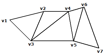
Creates a triangle strip, which is a series of connected triangular faces. These faces are defined by three consecutive points in a point list. The first three vertices (labeled below as v1, v2, and v3), define the first triangular face. A new triangle is formed by connecting the next point with its two immediate predecessors. That is, every additional point vi defines a new triangular face with vertices vi–2, vi–1, and vi. For example, the second triangle is defined by v2, v3, v4, the third by v3, v4, v5, etc. The following diagram illustrates a typical Triangle Strip.
The orientation of the entire triangle strip is determined by the orientation of the first triangle. If the vertices of the first triangle are ordered counterclockwise, then the front of the strip is displayed; otherwise, the back of the strip is displayed. If the triangle strip has been flipped, then the front/back of the entire strip is actually the reverse of what the first triangle indicates. |
|||||||||||||||||||||
|
Triangle Fan |
Creates a triangular fan, which is a series of connected triangular faces. The fan differs from a Triangle Strip in the way that vertices define faces. The first three vertices (labelled below as v1, v2, and v3), define the first triangular face. A new triangle is formed by connecting the next point with its immediate predecessor and the first point of the triangle fan. That is, every additional point vi defines a new triangular face with vertices v1, vi-1, and vi. For example, the second triangle is defined by v1, v3, v4, the third by v1, v4, v5, etc. The following diagram illustrates a typical Triangle Fan.
The orientation of the entire triangle fan is determined by the order of vertices of any triangle within the fan (all the triangles are already oriented in the same direction). When they are ordered counterclockwise, the front is displayed; otherwise, the back is displayed. |
|||||||||||||||||||||
|
Face |
Creates a planar area in 3D space. The planar structure can be a polygon, an ellipse or a donut. The orientation of a Face is determined by using the following rule: if the fingers of your right hand curl along the order of the vertices, the direction that the thumb points to is the front of the face. This thumb direction also describes the surface normal of the face, a vector that points outwards perpendicular from the area. Curve closing method: This method controls how the curve is closed. It is applicable only if the first and last coordinates entered do not match X, Y or Z coordinate values. It ensures that the coordinates of the start and end points match so that it is a valid area. Average: The current start and end points are each replaced by the average of the start and end points. Extend: The start and end points are connected with no additional points. Extend or Average: The area is closed using the Average method if – and only if – the start and end points differ by at most one of X, Y, or Z. Otherwise, the Extend method is used to close the area. |
|||||||||||||||||||||
| Clothoid |
Creates a clothoid which are curves whose curvature changes linearly as a function of length. A clothoid in FME is defined by start curvature, end curvature, clothoid length, start position, and start direction. To create a clothoid whose elevation is a linear function of length, start/end elevations may also be defined. An optional transformation matrix can be specified. |
|||||||||||||||||||||
|
Custom |
Creates an object based on an XML representation. |
Creates either 2D geometry or 2D geometry with z-values, depending on your choice in the Geometry Source parameter. Enter a space-delimited list of x y (z) coordinates.
This parameter allows you to set the coordinate system on the specified feature. Select a coordinate system from the pull-down list, or click the Browse button to select from the Coordinate System Gallery. If you leave this parameter blank, the coordinate system will not be set on the feature(s) created by this transformer.
This parameter specifies how many features will be created. When more than one feature is created, the attribute specified by the Creation Instance Attribute parameter will hold each feature's creation number (starting from 0).
Create at End determines whether the feature is created after all reader features have been processed (Yes), or whether the feature is created immediately before the first reader feature is processed (No).
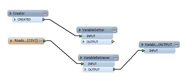
Features cannot be created in the data flow before any reader reads anything, since the data flow is driven by features arriving from the reader.
In rare cases, you might want the Creator to specifically operate before other features are processed.
The workspace shown here is trying to combine two paths of features through the VariableSetter and VariableRetriever. The problem is that FME's data flow was not designed to consider multiple feature paths and so, no matter what the setting is for the Create at End parameter, the Creator always creates its feature after the reader.

However, if you specifically want the Creator to create a feature first, you can include it in the same data flow as the reader features.
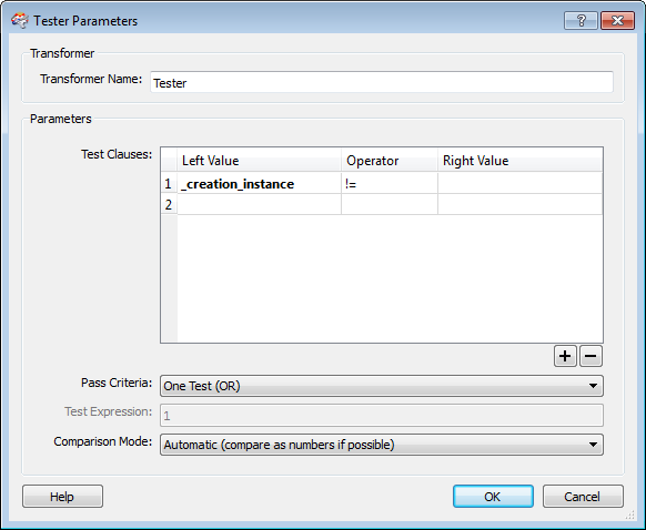
A Tester is added to both the Creator data flow and the reader data flow:

In the modified workspace shown below, the feature from the Creator data flow will be discarded through the Tester's FAILED port and features from the reader data flow will continue – however, the features will now be processed either before or after the Creator, depending on the chosen setting in the Create at End parameter.

When more than one feature is created (see the Number to Create parameter above), this attribute will hold each feature's creation number (starting from 0).
Editing Transformer Parameters
Using a set of menu options, transformer parameters can be assigned by referencing other elements in the workspace. More advanced functions, such as an advanced editor and an arithmetic editor, are also available in some transformers. To access a menu of these options, click  beside the applicable parameter. For more information, see Transformer Parameter Menu Options.
Transformer Categories
Search FME Community
Search for samples and information about this transformer on the FME Community.

