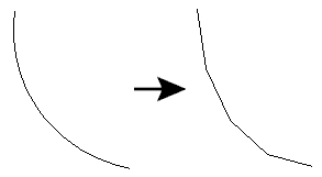
Converts arc features into lines replacing the feature geometry with a series of edges interpolated along the arc boundary. Ellipse features are converted into polygons by interpolating edges along the elliptical boundary.
If the input geometry is a path consisting of arcs and lines, or an area whose boundary is such a path, then any arcs in the path will be stroked, also using the Number of Interpolated Edges given.
Input Ports
This transformer accepts features with arc or ellipse geometry. Other features are unchanged.
Output Ports
All point, line, and area features are output through this port.
All features that are not points, lines, or areas are output through this port.
Parameters
You can convert arc or ellipse features into lines either by specifying the Number of Interpolated Edges or the Maximum Deviation.
The Number of Interpolated Edges and the Maximum Deviation may either be entered as a number, or can be taken from the value of a feature attribute by selecting the attribute name from the pull-down list.
If this parameter is specified and set to 0, then a reasonable number of edges will be interpolated for the arc.
If the Maximum Deviation is specified and has a value greater than 0, then arcs are converted into lines such that the maximum distance between the lines and the arcs is not greater than the value specified. If the Maximum Deviation value is greater than the primary or secondary axis of the arc or ellipse, then the converted lines will have minimum number of edges possible. If the Maximum Deviation value is smaller than or equal to 0, then the value of the Stroke Maximum Deviation advanced setting set in the workspace is used. If both values are smaller than or equal to 0, then arcs are converted into lines using the Number of Interpolated Edges value of 0.
If this parameter is set to Yes, then arc features with a 360-degree sweep angle are converted into polygons. Otherwise, they are converted into lines.
Example

Editing Transformer Parameters
Using a set of menu options, transformer parameters can be assigned by referencing other elements in the workspace. More advanced functions, such as an advanced editor and an arithmetic editor, are also available in some transformers. To access a menu of these options, click  beside the applicable parameter. For more information, see Transformer Parameter Menu Options.
Transformer Categories
Search FME Community
Search for samples and information about this transformer on the FME Community.