Group Elements By
Specifies the overall structure of the schema and data for DGN file reading.
The schema will be generated using level numbers in the source dataset as FME feature types.
The schema will be generated using level names in the source dataset as FME feature types.
The schema will be generated using all the possible Design geometry types as FME feature types. This list is set by the reader capability and is not limited to geometries which occur in the given source dataset.
The schema will be generated using both the level numbers and elements in the source dataset. The level numbers will be used to create FME feature types as in the Group by Level selection; however, the attributes of all the elements belonging to a level will be accumulated and also added to the FME feature type for that level.
The schema will be generated using both the names and elements in the source dataset. The level names will be used to create FME feature types as in the Group by Level Names selection; however, the attributes of all the elements belonging to a level will be accumulated and also added to the FME feature type for that level.
Element Options
The reader can be configured to output all the elements composing cells, or symbols. This is useful if the graphical representation of the Design file is to be preserved. This is true when, for example, a Design file is translated to a GIF image.
Select this option to expand the cells into separate features.
Preserve Named Cell Insert Points
When selected, outputs the insertion point of the named cell.
Preserve Unnamed Cell Insert Points
When selected, outputs the insertion point of the unnamed cell.
Read Reference up to First Level: (Deprecated: Superseded by the parameter Max Depth of Reference Files to Read)
Reads all the supported elements in the external reference files attached to the source dataset up to the first level of nesting only. This parameter is valid only if Read Elements from Reference Files is selected.
Specifies reading of supported elements from the external reference files attached to the source dataset for a number of levels. Files referenced by the source dataset are considered level 1, and nested references are considered further levels.
This parameter is valid only if Read Elements from Reference Files is selected.
This parameter is applicable to version 8 only.
When selected, reads any external reference files attached to the source dataset as features with an igds_type of igds_xref.
Note: The reading of all supported elements in external reference files is affected by the Read Elements From Reference Files parameter (not this parameter).
Select this option to display tags. Elements in a design file may have user-defined attributes attached to them, in a form called Tags. FME can read (but not write) these attributes. In addition, to supply a value for a user-defined attribute, tags may also be displayed as text in the original design file.
When reading a design file, FME first scans for all the tag data elements and tag set definition elements. Then as it reads each graphical element from the design file, it uses the element association ID to reconnect the data and attribute names with the graphical element. All the tag data values are then added to the feature returned into FME.
Attribute Options
Read Tag element data as attributes.
This parameter is applicable to version 8 only.
Select this option to read XAttribute information. Elements in a design file may have user-defined attributes attached to them in a form called XAttributes. Such attributes can be read (but not written) by FME. They are represented as list attributes, and contain various typed information chunks such as XML fragments, as is the case when they represent XML-based Feature Modeling (XFM) data.
Linkage Extraction
Linkage Extraction boxes allows you to extract MSLinks and/or FRAMME attribute linkage values from the Source Design File. Only the first three linkage values will be extracted.
These linkage values can be used to join the graphical data held in the design file to the MSLINK field in the related database table. The entity number that is extracted is used to determine the relevant table that holds the attributes (the database contains a table called MSCATALOG which maps entity numbers to table names).
The UFID is extracted together with the basename of the design file. These two items form a compound key that can be joined to the related FRAMME database.
Coordinate Units By
These parameters control the conversion between UORs in the Design file and FME coordinates. There are three possibilities:
Note that for each of these conversions, the coordinates of an FME feature will represent the coordinates as scaled by the UOR to FME Units Scale Factor. Those coordinates are all relative to working coordinates.
| Coordinate Units Value | Description |
|
Master |
The UORs read from the Design file are converted into master units, according to the conversion factor read from the Design file header, before being stored in an FME feature. |
|
Sub |
The UORs read from the Design file are converted into subunits, according to the conversion factor read from the Design file header, before being stored in an FME feature. |
|
UOR |
The UORs read from the Design file are stored directly in an FME feature with no conversion. |
Override Global Origin
These parameters are usually used only when reading Design files that have bad header information. If FME detects a difference between these settings and those read from the Design file, a warning is output to the log file, and these settings take precedence.
You can override the global origin, which is by default at the center of the design plane/cube, by setting the values of X, Y, and Z. Setting these values overwrites the global origin as read from the .dgn file. Valid values are unsigned 32-bit integers.
- X: The global origin of X, measured in UORs, from the lower left corner of the design plane/cube.
- Y: The global origin of Y, measured in UORs, from the lower left corner of the design plane/cube.
- Z: The global origin of Z, measured in UORs, from the lower left corner of the design plane/cube.
Schema Attributes
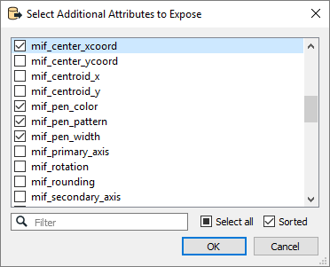
Use this parameter to expose Format Attributes in Workbench when you create a workspace:
- In a dynamic scenario, it means these attributes can be passed to the output dataset at runtime.
- In a non-dynamic scenario, you can use this parameter to expose additional attributes on multiple feature types.

Use Search Envelope
Using the minimum and maximum x and y parameters, define a bounding box that will be used to filter the input features. Only features that intersect with the bounding box are returned.
If all four coordinates of the search envelope are specified as 0, the search envelope will be disabled.
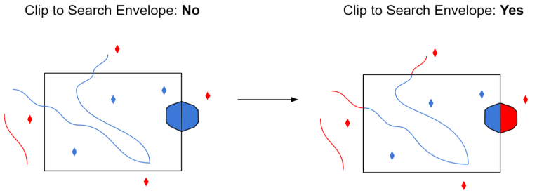
When selected, this parameter removes any portions of imported features being read that are outside the Search Envelope.
The example below illustrates the results of the Search Envelope when Clip to Search Envelope is not selected (set to No) and when it is selected (set to Yes).
- No: Any features that cross the search envelope boundary will be read, including the portion that lies outside of the boundary.
- Yes: Any features that cross the search envelope boundary will be clipped at the boundary, and only the portion that lies inside the boundary will be read. The underlying function for the Clip to Search Envelope function is an intersection; however, when Clip to Search Envelope is selected, a clipping operation is also performed in addition to the intersection.

Advanced
When selected, each component of a complex chain to be returned as its own feature and no feature will be returned for the complex chain as a whole.
When deselected, all elements of the complex chain will be merged into a single linear feature, any arcs in the complex chain will be converted into linestrings, and any linkages on the component elements themselves will be lost.
When selected, the reader splits the multi-text into text nodes and outputs the member text elements as individual text elements. If the multi-text had any linkage attributes, these will be propagated to the component elements.
When deselected, the text elements are not split.
Controls the way the dimensions are imported.
When selected, the dimensions are exploded into its pieces.
When deselected, the dimensions are imported as an aggregate. When dimensions are imported as aggregates, the arcs are stroked and text features are output as list attributes only. For example, if you're performing a DGN-to-DGN translation and you do not select this option, the text features will be lost.
Select this parameter if you have an Esri World file (*.wld) that you want FME to use when determining the coordinates for features in your dataset.
FME will search the folder of the dataset for a file with the same name as your dataset but with a .wld extension. If it cannot find a file with that name, it will then look for the file esri_cad.wld within the dataset folder. If either of those files exists, FME will use the information in the files to translate the coordinates of the features in the dataset to their new geospatial coordinates.
If the files cannot be found, then the translation will continue, using the coordinate information found in the dataset, without performing any additional transformation.
This parameter controls whether or not curve elements will be stroked into lines by adding vertices.
When selected, the control points of the curve are connected into a line. This option preserves the original control points and the end slopes. This is primarily used for DGN-to-DGN translations.
When deselected, The control points are used to interpolate a linear representation of the curve. It strokes (vectorizes) the curve (that is, it preserves the shape of the curve). Deselecting this checkbox enables the parameter Number of interpolated curve vertices.
Remove the duplicate points (same x and y coordinates) from the geometry of the feature.
When selected, allow the assumption that working units are equal to master units. This affects all calculations involving conversion from UOR coordinates to coordinates of any known unit, such as when the UORs Per Sub Unit or UORs Per Master Unit parameters are defined.
When deselected, the working unit of the Design file will be additionally used in the calculation of coordinates.
The number of ground units per UOR. Valid value: a double-precision floating point number.
The number of UORs per sub unit. Valid value: an unsigned integer ratio.
This parameter is used only if UOR to FME Units Scale Factor is not present.
The number of sub units per master unit. Valid value: an unsigned integer ratio.
This parameter is used only if UOR to FME Units Scale Factor is not present.
If an elevation shift is desired to build "fake" 3D topology, this is the scaling factor used to generate the shift.
Specifically, the Z value is divided by this factor and the result is added to the X value.
This parameter controls the number of points per segment when the curve is interpolated into a line. Used when Preserve Curves is not selected.