All linear features produced by this transformer are sent to the Line port.
Takes lines and connects them to form longer lines. Each connecting line must meet at the exact same start/end point, but otherwise they must not intersect.
Any nodes with only two lines connecting to them (sometimes called pseudonodes) are removed. Lines remain broken at points where three or more converge.
Note: Duplicate lines passed into the transformer will be consumed by the transformer.
All linear features produced by this transformer are sent to the Line port.
The Group By list of attributes separates the input data into sets which are considered independently when the node removal is done. Only attributes that are listed in the Group By list will be passed to subsequent transformers – all other attributes are removed.
Note: How parallel processing works with FME: see About Parallel Processing for detailed information.
This parameter determines whether or not the transformer should perform the work across parallel processes. If it is enabled, a process will be launched for each group specified by the Group By parameter.
For example, on a quad-core machine, minimal parallelism will result in two simultaneous FME processes. Extreme parallelism on an 8-core machine would result in 16 simultaneous processes.
You can experiment with this feature and view the information in the Windows Task Manager and the Workbench Log window.
No: This is the default behavior. Processing will only occur in this transformer once all input is present.
By Group: This transformer will process input groups in order. Changes on the value of the Group By parameter on the input stream will trigger batch processing on the currently accumulating group. This will improve overall speed if groups are large/complex, but could cause undesired behavior if input groups are not truly ordered.
This parameter controls whether or not lines can be reversed in order to create longer lines. If the direction of the lines is significant, then choose Yes.
This parameter indicates whether any resulting (or input) closed rings should ever be broken into two segments:
This parameter specifies whether to consider the node elevation when combining lines. Nodes that share the same location but have different elevations will not be combined if this option is set to Yes. If set to No, then the Connect Z mode parameter will specify how to combine nodes that lie on top of each other but have differing elevations.
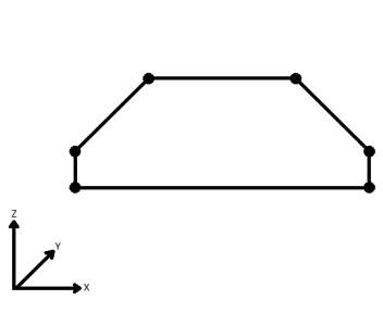
When viewed in 2D (ignoring Z), a path (which may define the border of a polygon) may appear to be closed as shown in the left figure below. This same path, when viewed in 3D, may appear to be open as shown in the right figure below.
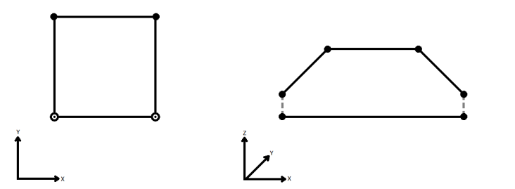
To specify how (and if) paths should be closed in 3D, select one of the listed modes.
| Mode | Description | Example |
|---|---|---|
| Extend | The Curve is extended so that all vertices are left at their original location. |
|
| Average | Subsequent vertices that are not connected, but share an x and a y value are combined into one vertex, whose Z value is the average of the original two. |

|
| First Wins | Subsequent vertices that are not connected, but share an x and a y value are combined into one vertex, whose Z value is taken from the first encountered vertex. |

|
| Last Wins | Subsequent vertices that are not connected, but share an x and a y value are combined into one vertex, whose Z value is taken from the last encountered vertex. |
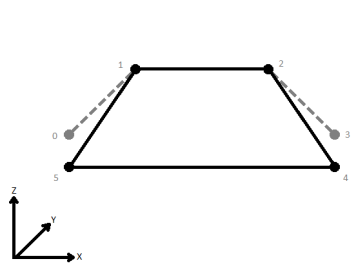
|
| Ignore | Z values are ignored. No change is made to the way the nodes are connected. |

|
Input Feature Topology indicates the type of vertices the input features contain:
If a List Name is given, an attribute list is created on each output with an entry for each feature contributing to that output line, and attributes are merged as base attributes on the output features. Otherwise, no attributes besides the Group By attributes are added to the output features.
Note: List attributes are not accessible from the output schema in Workbench unless they are first processed using a transformer that operates on them, such as ListExploder or ListConcatenator. All list attribute transformers are displayed in the Contents pane of the Transformer Help under Lists. Alternatively, AttributeExposer can be used.
If set to Yes, then when lines originating from different input curves are concatenated into a longer curve in the output, they will be left as separate segments in a path. The default is No, which means that such lines will be joined into longer lines in the output unless they have different properties (for example, traits, measures, geometry name).

Using a set of menu options, transformer parameters can be assigned by referencing other elements in the workspace. More advanced functions, such as an advanced editor and an arithmetic editor, are also available in some transformers. To access a menu of these options, click  beside the applicable parameter. For more information, see Transformer Parameter Menu Options.
Associated FME function or factory: ArcFactory
Search for samples and information about this transformer on the FME Knowledge Center.
Tags Keywords: connectivity ring PseudoNodeRemover LineJoiner