Constructs a Delaunay triangulation based on input points and breaklines.
The surface model may be output in a variety of representations, such as a triangulated irregular network (TIN), TIN vertices, triangles, digital elevation model (DEM), and contours. Because the surface model is a Delaunay triangulation, it can also be output as its dual – a Voronoi diagram.
When you need multiple representations of a surface model, this transformer is more efficient than using separate transformers.
Tip: If a connection exists on this output port, the parameter Conflict Resolution is activated. This parameter can filter out a subset of input POINTS/LINES to ensure a well-constructed surface model.
SurfaceModel.vertex1_id and SurfaceModel.vertex2_id, which identify the vertices to which it is connected.| SurfaceModel.vertex1_id, SurfaceModel.vertex2_id, and SurfaceModel.vertex3_id | identify the vertices that define the triangle |
| SurfaceModel.slope | the slope of the plane defined by the triangle, in degrees, relative to the horizontal plane |
| SurfaceModel.percentageSlope | the slope expressed as ( rise / run ) * 100%, or equivalently tan( SurfaceModel.slope ) * 100% |
| SurfaceModel.aspect | the aspect angle, in degrees, measured by the angle between nx and ny, where nx and ny are are the x and y components of the normal vector of the triangle |
SurfaceModel.vertex_id which uniquely identifies the vertex.| SurfaceModel.vertex_id | identifies the vertices that it encloses |
| SurfaceModel.elevation | contains the elevation of the enclosed vertex |
This parameter allows groups to be formed by attribute values. Zero or more attributes may be specified.
Input features with the same attribute values are placed into the same group. The transformer then operates independently on each group of input features.
If this parameter is left blank, the transformer will treat the entire set of input features as one group.
How parallel processing works with FME: see About Parallel Processing for detailed information.
This parameter determines whether or not the transformer should perform the work across parallel processes. If it is enabled, a process will be launched for each group specified by the Group By parameter.
| Parameter | Number of Processes |
|---|---|
| No Parallelism | 1 |
| Minimal | coresThe processor, or CPU, is the physical part of the computer that performs mathematical calculations. It is the most important part of a computer system. Traditional processors have only one core on the processor, meaning that at any given time, only one set of calculations is being performed. If a processor is dual-core, this means the single chip contains hardware for two processors, now called cores to distinguish them from the single chip, running simultaneously, side by side. (Source: http://www.ehow.com/facts_5730257_computer-core-processors_.html) / 2 |
| Moderate | exact number of cores |
| Aggressive | cores x 1.5 |
| Extreme | cores x 2 |
For example, on a quad-core machine, minimal parallelism will result in two simultaneous FME processes. Extreme parallelism on an 8-core machine would result in 16 simultaneous processes.
You can experiment with this feature and view the information in the Windows Task Manager and the Workbench Log window.
This parameter is used to determine which input points to add to the surface model as vertices. Specifying a value of 0 turns off vertex filtering.
Tip: A larger value will speed up surface model construction. The larger the value, the more input points will be filtered out. For input files with millions – or even billions – of points, it becomes essential to increase this value.
When a positive value for surface tolerance is specified, it works as follows. For each vertex that is being added to the model:
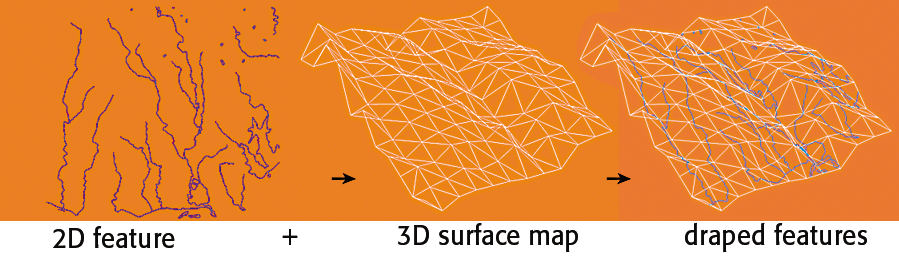
This parameter controls whether input DRAPE_FEATURES will retain its vertex count, or be modified to adhere to the underlying surface model:
This parameter is used for the output ports DEM_POINTS and DEM_RASTER when these output ports exist on the transformer. It is also used if DRAPE_FEATURES are input to the model.
This parameter specifies the name of an elevation attribute for the output ports CONTOURS and DEM_POINTS, when these output ports exist on the transformer.
This parameter specifies the elevation separation of the output contours.
This parameter specifies whether the output contours are 2D or 3D. 2D contours are equivalent to 3D contours, except that the z coordinates are dropped.
Tip: When the input dataset is large enough, setting this parameter to 2D will result in a visible performance improvement.
This parameter controls whether input points on the contour interval are dropped, or perturbed. Not dropping or perturbing these points would result in topologically invalid contours.
These parameters specify the x and y sampling intervals for the output DEM_POINTS.
This parameter is used only when Interpolation Method is set to PLANAR, and it only affects the output port DEM_RASTER.
All output raster cells that fall outside the underlying surface model’s boundaries will be assigned the value of this parameter.
When this parameter is blank, it is interpreted as NaN.
Note: To ensure consistent raster output, it is highly recommended that you do not leave this parameter blank.
This parameter allows you to define a file for storing a surface model.
File storage is useful for building a large surface model through multiple runs, and for workspaces that need to re-use a preconstructed surface model. The saved surface models can be used as part of a production stream on the same operating system.
Note: This parameter is processed only if Group By is not specified.
This parameter specifies the filename, including its path, of the surface model file. The surface model file has the file extension *.fsm.
This parameter controls whether the workspace is reading or writing a surface model file.
Note: There must be at least one input feature. For reading, it suffices to input a null feature via any of the input ports.
This parameter provides an estimate of the number of vertices in the final surface model, which can be significantly greater than the total number of input points through POINTS/LINES and BREAKLINES.
Note: A generous estimate is recommended when you are building a large model in multiple runs because this estimate is used for optimization purposes. If this estimate is too low, the surface model construction could take significantly longer.
This parameter should only be used when you are building large surface models across multiple runs.
Note: In subsequent runs of the SurfaceModeller, this parameter must be specified or else the transformer will use the bounding box of the surface model from the first run for constructing the surface model.
It is important to note that if the only thing you want to do with an existing surface model is output information, then you must route a feature into the surface model. The easiest way to do this is to simply use the Creator transformer and route a single NULL Geometry feature into the DRAPE_FEATURES input port.
About Transformer Parameter Options
FME Professional edition and above
Search for samples and information about this transformer on FMEpedia.
Keywords: MBR "minimum bounding rectangle"
Keywords: MBR "minimum bounding rectangle"