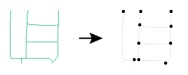
Computes intersections between all input features, breaking lines and polygons wherever an intersection occurs. In addition, all overlapping segments are reduced to one segment before being output.
If you select Group By attributes, only those features with the same Group By attribute values will be processed. If you do not select Group By attributes, then all features will be processed.
How parallel processing works with FME: see About Parallel Processing for detailed information.
This parameter determines whether or not the transformer should perform the work across parallel processes. If it is enabled, a process will be launched for each group specified by the Group By parameter.
| Parameter | Number of Processes |
|---|---|
| No Parallelism | 1 |
| Minimal | coresThe processor, or CPU, is the physical part of the computer that performs mathematical calculations. It is the most important part of a computer system. Traditional processors have only one core on the processor, meaning that at any given time, only one set of calculations is being performed. If a processor is dual-core, this means the single chip contains hardware for two processors, now called cores to distinguish them from the single chip, running simultaneously, side by side. (Source: http://www.ehow.com/facts_5730257_computer-core-processors_.html) / 2 |
| Moderate | exact number of cores |
| Aggressive | cores x 1.5 |
| Extreme | cores x 2 |
For example, on a quad-core machine, minimal parallelism will result in two simultaneous FME processes. Extreme parallelism on an 8-core machine would result in 16 simultaneous processes.
You can experiment with this feature and view the information in the Windows Task Manager and the Workbench Log window.
The creation of nodes can be calculated in 3D, if requested. Constructing nodes in 3D would mean that line segments would only share a node if they shared the same Z value at the point they intersected. Constructing nodes in 2D would mean that all intersecting segments would share a common node, regardless of their respective Z values.
Consider, for example, a situation where two lines (that crossed) represented roads, where one road was an overpass above the other road. Suppose these two lines had differing elevations. If you constructed nodes in 3D, these two roads would not be linked to the same node where they crossed. Two nodes would be produced at the crossing point – each one with a different Z value. If you constructed nodes in 2D, these lines would both link to a common node, which would be present at the location where they crossed. In either the 2D or 3D case, the full dimensionality of the input is preserved in the output – 3D features are never converted to 2D. The 2D or 3D choice only indicates how the nodes are created and which lines are linked to them; it does not affect the dimension of the features that are output.
If the Duplicate Nodes at Each Elevation parameter is set to Yes, then whenever 3D lines intersect at differing heights, two 2D nodes will be output via the NODE port. Each node will have the same x and y coordinates, but a different node number.
If the Duplicate Nodes at Each Elevation parameter is set to No, then whenever 3D lines intersect at differing heights, a single 2D node is output at the intersection point.
The Overlap Count Attribute parameter names an attribute that will be added by the transformer, containing the number of collinear input lines that overlapped the output segment.
The Segment Count Attribute parameter, if specified, names an attribute that will be added by the transformer, containing the number of segments into which the segment’s original feature was divided.
If an input feature was broken into n output segments, each of those segments will have an attribute named <attribute name> which has a value of n.
If the optional list name is supplied, a list of all the attributes of each lines which overlapped an output segment is made. This allows later inspection of overlapping segment attributes.
This parameter causes overlapping segments not to be merged into a single segment: one copy is output for each original feature sharing the segment. Each such segment will have the respective original feature’s attributes as its main attributes, and attributes from all other collinear features will be added as a list attribute, if the list name was supplied.
When a coverage of polygons is input, the set of topologically significant lines which form their boundaries is output.
If the Split Self-Intersecting Features parameter is set to Yes, self-intersections in the input features are removed by splitting the feature.
No feature-to-feature comparisons are made. In this case, the value set to the Overlap Count Attribute will be the number of features that result from removing self-intersections. If the feature did not self-intersect, the attribute will be set to 1.
If the segment had several overlapping input features, the attributes of each of the input features will be added to the feature in the list identified by List Name, if one was specified. In any case, each output feature is also assigned the attributes of one of its original input features. This transformer also adds a "direction" attribute for each attribute resulting from the List Name parameter, labelling it as same if the geometry is oriented in the same direction, and opposite if the geometry is oriented in the opposite direction to the current geometry.
What if you have linear street centerlines and, at each intersection point, you'd like to know which streets come together? The output should be a set of points, each with a single string attribute containing a comma-separated set of the street names.
You can solve this by setting up a workspace that routes all the street centerlines into an Intersector. Adjust the parameters of the Intersector to supply a list name; for example, all_streets.
Let's assume that the input street lines had an attribute called NAME. Now, among other things, the NODE output of the Intersector will have an unqualified list on it called all_streets{}.NAME. This list will hold the names of all the streets that intersect at each particular point (or NODE) that is output.
To turn the list of NAMEs into a single string, add a ListConcatenator transformer and run the NODE features into it. Then set up the ListConcatenator's parameters so that it would put the contents of the all_streets{}.NAME list together, separated by commas, into the "result" attribute. Then route the output of the ListConcatenator to an output file, and ensure that the "result" attribute was routed to an attribute in the output. After running the translation, you will have the desired result.
Note that you could also access the individual street names by "exposing" some elements of your list (by right clicking on the attribute unqualified list name (in our example, "all_streets{}.NAME") and saying "Expose Elements", and entering the number of elements to expose. You'd then have to do something with those elements in your translation. (The disadvantage of this approach is that you need to know ahead of time how many list elements you want to work with -- so if 3 streets intersect at the same node and you only set yourself up to handle two, you'd have to do something special to handle that.)
If the Advanced setting Geometry Handling is set to Enhanced in the workspace, arcs and ellipses will remain as arcs and ellipses; they will otherwise be stroked to lines and areas, respectively.
About Transformer Parameter Options
Search for samples and information about this transformer on FMEpedia.