FME Transformers: 2026.2
Cuts holes in surface features with other surface features. A surface that is cut by another surface must be co-planar with that second surface, and contain that second surface.

All surfaces are converted into faces (for example, a mesh is converted into faces – one face per mesh part).
Example
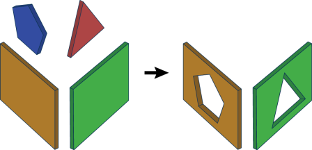
The example below illustrates the input features on the left and the output features on the right. The input consists of surface features that are coplanar. The output consists of features with cut holes wherever the surface features were contained within or intersected other surface features.
Usage Notes
-
To build a TIN (triangulated irregular network) surface from points, lines, and/or rasters, see the TINGenerator and SurfaceModeller.
Configuration
Input Ports
Surface features: it is assumed that any two input surfaces within a group either have a strict containment relationship, or are not overlapping.
Output Ports
Contains the output surfaces.
All but one geometrically identical surface will be output through the Unused port. Two surfaces are considered geometrically identical if their geometries match exactly.
Non-geometry properties like coordinate systems, measures, traits, and geometry labels are not considered when matching input geometries.
Non-surface features
Parameters
|
Group By |
Leaving this parameter blank causes the entire set of input surfaces to form a single group. Alternatively, this parameter allows you to select attributes on which to form groups of surface features – each set of features that have the same value for all of these attributes will be processed independently in a group. |
||||
|
Complete Groups |
Select the point in processing at which groups are processed:
There are two typical reasons for using When Group Changes (Advanced) . The first is incoming data that is intended to be processed in groups (and is already so ordered). In this case, the structure dictates Group By usage - not performance considerations. The second possible reason is potential performance gains. Performance gains are most likely when the data is already sorted (or read using a SQL ORDER BY statement) since less work is required of FME. If the data needs ordering, it can be sorted in the workspace (though the added processing overhead may negate any gains). Sorting becomes more difficult according to the number of data streams. Multiple streams of data could be almost impossible to sort into the correct order, since all features matching a Group By value need to arrive before any features (of any feature type or dataset) belonging to the next group. In this case, using Group By with When All Features Received may be the equivalent and simpler approach. Note Multiple feature types and features from multiple datasets will not generally naturally occur in the correct order.
As with many scenarios, testing different approaches in your workspace with your data is the only definitive way to identify performance gains. |
|
Enable Tolerance |
If set to Yes, the Normal Tolerance in Degrees and Offset Tolerance parameters are enabled. If set to No, the two parameters are disabled. |
|
Normal Tolerance in Degrees |
Faces must be parallel before they are allowed to cut into each other. If two faces are nearly parallel with normals that are slightly apart, use this parameter to set a tolerance in degrees. The larger the value, the less parallel the faces would have to be while still considered parallel to each other. Usage Tip: Use this parameter together with Offset Tolerance. |
|
Offset Tolerance |
Faces must be co-planar before they are allowed to cut into each other. If two faces are nearly co-planar, but are a small offset from each other, use this parameter to set a tolerance in ground units. The larger the value, the farther away the faces could be while still considered co-planar. Usage Tip: Use this parameter together with Normal Tolerance in Degrees. |
|
Drop Holes |
This parameter indicates whether or not surface features used to cut other surfaces should be dropped or output. |
Generate List
When enabled, adds a list attribute to the output surface, retaining attribute values for each input feature that became a hole, in the order that the holes appear.
|
Hole List Name |
Enter a name for the list attribute. Note List attributes are not accessible from the output schema in FME Workbench until they are exposed with an AttributeExposer or processed with a transformer that operates on them, such as a ListExploder or ListConcatenator.
|
|
Add To Hole List |
All Attributes: All attributes will be added to the output features. Selected Attributes: Enables the Selected Attributes parameter, where specific attributes may be chosen for inclusion. |
|
Selected Attributes |
Enabled when Add To Hole List is set to Selected Attributes. Specify the attributes you wish to be included. |
|
Hole Flag Attribute |
Name the attribute that will contain "yes" if that feature was used to cut a hole inside some other feature, and "no" if that feature did not cut into any other features. |
Editing Transformer Parameters
Transformer parameters can be set by directly entering values, using expressions, or referencing other elements in the workspace such as attribute values or user parameters. Various editors and context menus are available to assist. To see what is available, click  beside the applicable parameter.
Defining Values
There are several ways to define a value for use in a Transformer. The simplest is to simply type in a value or string, which can include functions of various types such as attribute references, math and string functions, and workspace parameters.
Using the Text Editor
The Text Editor provides a convenient way to construct text strings (including regular expressions) from various data sources, such as attributes, parameters, and constants, where the result is used directly inside a parameter.
Using the Arithmetic Editor
The Arithmetic Editor provides a convenient way to construct math expressions from various data sources, such as attributes, parameters, and feature functions, where the result is used directly inside a parameter.
Conditional Values
Set values depending on one or more test conditions that either pass or fail.
Parameter Condition Definition Dialog
Content
Expressions and strings can include a number of functions, characters, parameters, and more.
When setting values - whether entered directly in a parameter or constructed using one of the editors - strings and expressions containing String, Math, Date/Time or FME Feature Functions will have those functions evaluated. Therefore, the names of these functions (in the form @<function_name>) should not be used as literal string values.
| These functions manipulate and format strings. | |
|
Special Characters |
A set of control characters is available in the Text Editor. |
| Math functions are available in both editors. | |
| Date/Time Functions | Date and time functions are available in the Text Editor. |
| These operators are available in the Arithmetic Editor. | |
| These return primarily feature-specific values. | |
| FME and workspace-specific parameters may be used. | |
| Creating and Modifying User Parameters | Create your own editable parameters. |
Table Tools
Transformers with table-style parameters have additional tools for populating and manipulating values.
|
Row Reordering
|
Enabled once you have clicked on a row item. Choices include:
|
|
Cut, Copy, and Paste
|
Enabled once you have clicked on a row item. Choices include:
Cut, copy, and paste may be used within a transformer, or between transformers. |
|
Filter
|
Start typing a string, and the matrix will only display rows matching those characters. Searches all columns. This only affects the display of attributes within the transformer - it does not alter which attributes are output. |
|
Import
|
Import populates the table with a set of new attributes read from a dataset. Specific application varies between transformers. |
|
Reset/Refresh
|
Generally resets the table to its initial state, and may provide additional options to remove invalid entries. Behavior varies between transformers. |


Note: Not all tools are available in all transformers.
For more information, see Transformer Parameter Menu Options.
Reference
|
Processing Behavior |
|
|
Feature Holding |
Yes |
| Dependencies | None |
| Aliases | |
| History |
FME Online Resources
The FME Community and Support Center Knowledge Base have a wealth of information, including active forums with 35,000+ members and thousands of articles.
Search for all results about the SurfaceBuilder on the FME Community.
Examples may contain information licensed under the Open Government Licence – Vancouver, Open Government Licence - British Columbia, and/or Open Government Licence – Canada.