FME Transformers: 2025.0
Related Transformers
FaceReplacer
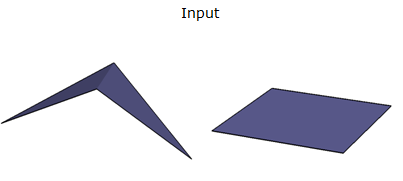
Filters features based on their planarity. To be planar, a geometry must have all its points situated in the same plane.
This transformer works only on the following geometries:
- points
- curves
- areas (polygons, ellipses, and donuts)
- multi-areas
- surfaces
- multi-surfaces
- composite surfaces
Configuration
Input Ports
Typically area-based or surface-based geometries.
Output
If an area-based or surface-based geometry has all of its points situated in the same plane, its features are sent to the Planar output port.
If an area-based or surface-based geometry is not planar, its features are written to the NotPlanar output port.
All features with geometry types other than points, curves, multi-curves, areas, multi-areas, surfaces, multi-surfaces, or composite surfaces will be sent to the <REJECTED> output port.
Parameters
|
Thickness Mode |
Select an option or choose an attribute. Automatic estimates a valid thickness for the geometry. Custom allows you to input your own thickness. Ignore ignores the thickness check entirely. |
|
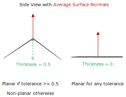
Thickness |
Enter a value or choose an attribute. The thickness tolerance is specified in ground units, and describes the maximum “thickness” a plane can have before it is considered non-planar. A planar polygon has a thickness of 0. A non-planar polygon will have its average surface normal computed using Newell’s method, and its thickness will be determined in the direction of the normalized surface normal. For example, consider a single, non-planar polygon. Imagine a plane that passes through the world origin, with its normal set to the average normal of the polygon. Then, every point along the polygon boundary would be a distance D to the world plane. Relative to the world plane, we find the closest point and the farthest point along the polygon boundary. The difference between the farthest and nearest distances give us the desired thickness.
|
|
Angular Mode |
Select an option or choose an attribute. Automatic estimates a valid surface normal deviation for the geometry. Custom allows you to input your own surface normal deviation (in degrees). Ignore ignores the surface normal check entirely. |
|
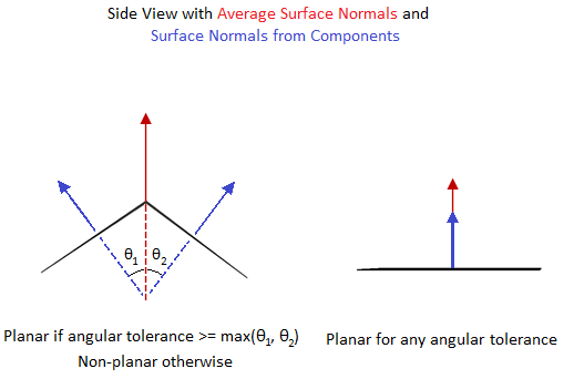
Surface Normal Deviation (degrees) |
Enter a value or choose an attribute. The surface normal deviation tolerance is specified in degrees, and describes the maximum deviation from the average surface normal that a component can have before it is considered non-planar. A planar polygon has a surface normal deviation of 0. A non-planar polygon will have its average surface normal computed using Newell’s method, and the surface normal deviation of each part from the average surface normal will be computed with the cosine law. For example, consider a single, non-planar polygon. Imagine a unit normal representing the average normal of the polygon. Now imagine a unit normal for each component of the polygon. The largest different between the average surface normal, and any other surface normal is the surface normal deviation.
|
If Specify Plane Normal is left unchecked, the average surface normal is determined using Newell’s method. In the case of surfaces with multiple components, such as MultiSurfaces or CompositeSurfaces, the average surface normal is determined from the first component. The effect is that coordinates must lie in the same plane, but that may be any plane.
If Specify Plane Normal is checked, then all coordinates must lie in a plane with the normal vector given by the Normal X, Y, and Z parameters. If the geometry contains multiple components, such as multi-surfaces, multi-areas, donuts, or composite surfaces, then each component must be coplanar with all of the other components, and must be within tolerance of the specified plane normal.
|
Normal X, Y, Z |
Sets the x, y, and z components of the vector normal specifying the plane against which to test. |
|
Expose Surface Normal |
If set to Yes, the Planar and NotPlanar outputs will have up to 6 extra attributes relating to the surface normal. If a non-degenerate surface normal was found, _surfaceNormalX, _surfaceNormalY, and _surfaceNormalZ indicate the vector that was used to perform the planarity check. _pointOnSurfaceX, _pointOnSurfaceY, and_pointOnSurfaceZ indicate a point on the surface. Together these entries can be used to define a vector that originates on the surface, and is collinear to the surface normal used to perform the planarity check. |
Editing Transformer Parameters
Transformer parameters can be set by directly entering values, using expressions, or referencing other elements in the workspace such as attribute values or user parameters. Various editors and context menus are available to assist. To see what is available, click  beside the applicable parameter.
Defining Values
There are several ways to define a value for use in a Transformer. The simplest is to simply type in a value or string, which can include functions of various types such as attribute references, math and string functions, and workspace parameters.
Using the Text Editor
The Text Editor provides a convenient way to construct text strings (including regular expressions) from various data sources, such as attributes, parameters, and constants, where the result is used directly inside a parameter.
Using the Arithmetic Editor
The Arithmetic Editor provides a convenient way to construct math expressions from various data sources, such as attributes, parameters, and feature functions, where the result is used directly inside a parameter.
Conditional Values
Set values depending on one or more test conditions that either pass or fail.
Parameter Condition Definition Dialog
Content
Expressions and strings can include a number of functions, characters, parameters, and more.
When setting values - whether entered directly in a parameter or constructed using one of the editors - strings and expressions containing String, Math, Date/Time or FME Feature Functions will have those functions evaluated. Therefore, the names of these functions (in the form @<function_name>) should not be used as literal string values.
| These functions manipulate and format strings. | |
|
Special Characters |
A set of control characters is available in the Text Editor. |
| Math functions are available in both editors. | |
| Date/Time Functions | Date and time functions are available in the Text Editor. |
| These operators are available in the Arithmetic Editor. | |
| These return primarily feature-specific values. | |
| FME and workspace-specific parameters may be used. | |
| Creating and Modifying User Parameters | Create your own editable parameters. |
Table Tools
Transformers with table-style parameters have additional tools for populating and manipulating values.
|
Row Reordering
|
Enabled once you have clicked on a row item. Choices include:
|
|
Cut, Copy, and Paste
|
Enabled once you have clicked on a row item. Choices include:
Cut, copy, and paste may be used within a transformer, or between transformers. |
|
Filter
|
Start typing a string, and the matrix will only display rows matching those characters. Searches all columns. This only affects the display of attributes within the transformer - it does not alter which attributes are output. |
|
Import
|
Import populates the table with a set of new attributes read from a dataset. Specific application varies between transformers. |
|
Reset/Refresh
|
Generally resets the table to its initial state, and may provide additional options to remove invalid entries. Behavior varies between transformers. |


Note: Not all tools are available in all transformers.
For more information, see Transformer Parameter Menu Options.
Reference
|
Processing Behavior |
|
|
Feature Holding |
No |
| Dependencies | None |
| Aliases | |
| History |
FME Community
The FME Community has a wealth of FME knowledge with over 20,000 active members worldwide. Get help with FME, share knowledge, and connect with users globally.
Search for all results about the PlanarityFilter on the FME Community.
Examples may contain information licensed under the Open Government Licence – Vancouver, Open Government Licence - British Columbia, and/or Open Government Licence – Canada.