Page Size
Specifies the size of the output page of the PDF document. The default value for this parameter is Letter.
You can select preset page sizes for common paper sizes or specify the page size in PostScript points in the format <width> <height>.
|
Paper |
Paper Size in Points |
|---|---|
| Letter | 612x792 |
| LetterSmall | 612x792 |
| Tabloid | 792x1224 |
| Ledger | 1224x792 |
| Legal | 612x1008 |
| Statement | 396x612 |
| Executive | 540x720 |
| A0 | 2384x3371 |
| A1 | 1685x2384 |
| A2 | 1190x1684 |
| A3 | 842x1190 |
| A4 | 595x842 |
| A4Small | 595x842 |
| A5 | 420x595 |
| B4 | 729x1032 |
| B5 | 516x729 |
| Folio | 612x936 |
| Quarto | 610x780 |
| 10x14 | 720x1008 |
This parameter determines where to place the map on the page, and how large the map should be on the page.
The format for the parameter is four integers separated by spaces describing the lower left corner and the upper right corner of the viewport/rectangle, specified in typographical points. The lower left corner of the page has coordinate (0,0) and the top right corner has coordinate (<width>,<height>) where these two values are the page size specified by the parameter Page Size.
If the aspect ratios of the page viewport and the world viewport differ, then the lesser scaling factor will be chosen: data inside the world viewport will not be clipped and data outside the world viewport might become visible.
If a value for the parameter is not specified, then the page viewport rectangle will be a centered rectangle with a width and length that is 90% of the page width and length. The page viewport coordinates must be between (0,0) and (page width,page height).
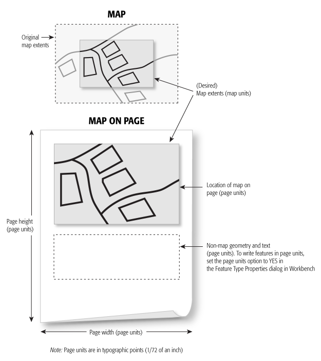
Values: <lowerLeftX> <lowerLeftY> <upperRightX> <upperRightY>
Specifies a rectangular region of space, in world coordinates, that will be mapped to the page viewport. Geometry outside the world viewport will be clipped when drawn on the page.
The format for this option is four floating point numbers, separated by spaces, describing the lower left corner and the upper right corner of the rectangle.
If a value is not specified, then the world viewport rectangle will be the bounding box of the entire dataset.
Values: <lowerLeftX> <lowerLeftY> <upperRightX> <upperRightY>
Map Parameters
Specifies the opacity value of the fill color of area geometries. The boundaries of area geometries are not affected by this setting.
A value of 0 corresponds to complete transparency and a value of 1 is complete opaqueness.
The default radius in pixels for point geometry.
The default width in pixels for line geometry and boundaries of area geometry.
Determines the panel that is visible immediately after opening the output PDF file in Adobe Acrobat software.
- None – The initial display will not contain a panel.
- Layers – The Layer panel will be visible after opening the file.
- Pages – The Page Thumbnails panel will be visible.
Specifies whether features without the fme_color attribute set will be assigned a random color based on its feature type.
Clearing this checkbox assigns the color "black" to features without defined fme_color attributes.
Text Parameters
Specifies whether the text size on the incoming feature is modified by the scale factors used to map the text location to the page location.
- If this option is left unchecked, the text size is determined solely from the input text geometry.
- If this option is checked, the text size from the input feature is additionally scaled by the world-to-page scale and may result in very large text that exceeds the page object bounds. Enabling this option is not generally recommended.
Specifies whether the text string of text features is in the rich text format. If the box is not checked, then the text string is written as-is to the page.
If this option is checked, then the text string will be processed for style directives.
Specifies additional folders that the writer will search to find the TrueType fonts used in the workspace.
Attribution
Specifies whether attribution data will be written. Not writing attribution data will decrease the file size of the output file and may improve viewing performance.
Compression
Determines whether streams in the output file will be compressed.
Compatibility
This parameter specifies whether or not to write files compatible with PDF 1.4 viewers.
By default, this parameter is not selected. This means that features introduced in PDF 1.5 and later will be used, including object stream compression and the JPEG2000 raster image format.
If this parameter is selected, the output file will not contain compressed object streams, cross-reference information is stored in a cross-reference table and xref trailer, and rasters are encoded in the JPEG format.
Spatial
Coordinate systems may be extracted from input feature data sources, may come predefined with FME, or may be user-defined. FME allows different output and input coordinate systems, and performs the required coordinate conversions when necessary.
If a coordinate system is specified in both the source format and the workspace, the coordinate system in the workspace is used. The coordinate system specified in the source format is not used, and a warning is logged. If a source coordinate system is not specified in the workspace and the format or system does not store coordinate system information, then the coordinate system is not set for the features that are read.
If a destination coordinate system is set and the feature has been tagged with a coordinate system, then a coordinate system conversion is performed to put the feature into the destination system. This happens right before the feature enters into the writer.
If the destination coordinate system was not set, then the features are written out in their original coordinate system.
If a destination coordinate system is set, but the source coordinate system was not specified in the workspace or stored in the source format, then no conversion is performed. The features are simply tagged with the output system name before being written to the output dataset.
For systems that know their coordinate system, the Coordinate System field will display Read from Source and FME will read the coordinate system from the source dataset. For most other input sources, the field will display Unknown (which simply means that FME will use default values). In most cases, the default value is all you'll need to perform the translation.
You can always choose to override the defaults and choose a new coordinate system. Select More Coordinate Systems from the drop-down menu to open the Coordinate System Gallery.
Changing a Reprojection
To perform a reprojection, FME typically uses the CS-MAP reprojection engine, which includes definitions for thousands of coordinate systems, with a large variety of projections, datums, ellipsoids, and units. However, GIS applications have slightly different algorithms for reprojecting data between different coordinate systems. To ensure that the data FME writes matches exactly to your existing data, you can use the reprojection engine from a different application.
To change the reprojection engine, Select Workspace Parameters > Spatial > Reprojection Engine. In the example shown, you can select Esri (but the selection here depends on your installed applications):

- The coordinate systems file coordsys.db in the FME installation folder contains the names and descriptions of all predefined coordinate systems.
- Some users may wish to use coordinate systems that do not ship with FME, and in those cases, FME also supports custom coordinate systems.
- Learn more about Working with Coordinate Systems in FME.