FME Transformers: 2024.1
Triangle Strip
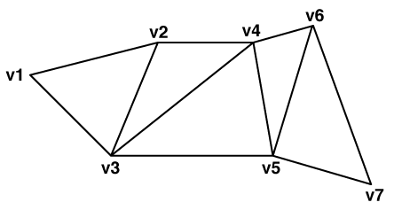
A triangle strip is a series of connected triangular faces. These faces are defined by three consecutive points in a point list. The first triangular face contains the first three vertices, denoted below by v1, v2, and v3. A new triangle is formed by connecting the next point with its two immediate predecessors. That is, every additional point vi defines a new triangular face containing vertices vi-2, vi–1, and vi.
For example, the second triangle contains v2, v3, and v4, the third contains v3, v4, and v5, and so on. The following diagram illustrates a typical triangle strip:

In order to maintain a consistent orientation, each successive triangle is defined with opposite orientation. In the diagram above, the vertex order would be (v1, v2, v3) for the first triangle, (v4, v3, v2) for the second, (v3, v4, v5) for the third, and so on. Due to this propagation, the overall orientation of a triangle strip can be determined by the orientation of the first triangle.
For information on how vertex order affects surface normal and front/back surface determination, see Faces. As a consequence of this, some triangle strips can only be directly defined in one direction and cannot be reversed without adding additional geometry under the default right-handed coordinate system (counter-clockwise winding order). In particular, triangle strips with an even length cannot be directly reversed. To mitigate this, triangle strips also store a flipped flag which defines whether the strip should use a left-handed coordinate system (clockwise winding) instead of right-handed.
Triangle strips may store measures on their nodes.
Triangle strips may possess optional front or back appearances, and may be single or double sided.