Security
DWF files support an optional password for additional security. When specified, the file cannot be opened without the password.
Paper Size
Specifies the maximum horizontal size in millimeters (mm) for the sheets read from the input DWF file.
Specifies the maximum vertical size in millimeters (mm) for the sheets read from the input DWF file.
Schema Attributes
Use this parameter to expose Format Attributes in FME Workbench when you create a workspace:
- In a dynamic scenario, it means these attributes can be passed to the output dataset at runtime.
- In a non-dynamic scenario, this parameter allows you to expose additional attributes on multiple feature types. Click the browse button to view the available format attributes (which are different for each format) for the reader.
A search envelope (also known as a bounding box) is a rectangular area that defines a geographic area. In FME, the easiest way to define a search envelope is to use search envelope parameters.
Defining a search envelope is the most efficient method of selecting an area of interest because FME will read only the data that is necessary – it does not have to read an entire dataset. Search Envelope parameters apply to both vector and raster datasets and can be particularly efficient if the source format has a spatial index.
Most FME readers have parameters to define the search envelope of data that is being read:
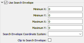
The parameters include the x and y coordinates of the bounding box as well as a parameter that defines the coordinate system.
How to Define the Bounding Box
Using the minimum and maximum x and y parameters, define a bounding box that will be used to filter the input features. Only features that intersect with the bounding box are returned. Note that the bounding box intersection is not a full geometry intersection (based on spatial relationships) that would be returned by a transformer like the SpatialFilter.
Search Envelope Coordinate System
Specifies the coordinate system of the search envelope if it is different than the coordinate system of the data. The coordinate system associated with the data to be read must always be set if this parameter is set.
If this parameter is set, the minimum and maximum points of the search envelope are reprojected from the Search Envelope Coordinate System to the reader’s coordinate system prior to applying the envelope.
The underlying function for Use Search Envelope is an intersection; however, when Clip to Search Envelope is checked, a clipping operation is also performed.
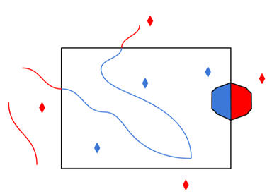
- When checked (set to Yes), this option instructs FME to clip features to the exact envelope boundary. FME removes any portions of imported features being read that are outside the search envelope.
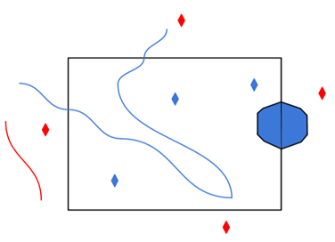
- When left unchecked (set to No), features that overlap the boundary will be included in their full (unclipped) form.
|
Clip to Search Envelope: No |
Clip to Search Envelope: Yes |
|---|---|
|
Any features that cross the search envelope boundary will be read, including the portion that lies outside of the boundary.
|
Any features that cross the search envelope boundary will be clipped at the boundary, and only the portion that lies inside the boundary will be read.
|
|
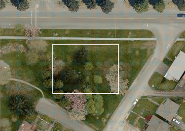
The search envelope includes the bounding box and the extent of the raster.
|
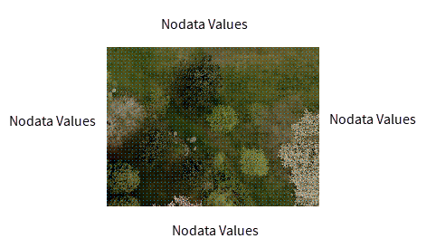
The search envelope includes only the area within the bounding box. The raster size will still match the bounding box, but the area without data will be filled with Nodata values to represent the absence of data, if the source raster has them. Raster Nodata may be a single value across all bands, a single value per band, or a separate alpha or transparency band that indicates the lack of data values (this is more common in images than other types of rasters).
|
Advanced
When selected, this parameter explodes blocks and return the entities that form the components of the block as separate features.
When the reader resolves blocks, it outputs a feature for each of the AutoCAD entities that is part of the block definition. The original insert is not output. This results in the full graphical representation of the block transferred through FME, but the exact insertion point of the block is lost.
Each block member feature is given the attribute autocad_block_number which is set to the same value for each block so that the features comprising each block may be combined in subsequent processing. Arbitrary deep block nesting is permitted, however, the autocad_block_number attribute is only updated for each block at the outermost level. By default, all block members will be on the same layer as that of the original block.
Usual AutoCAD-to-AutoCAD translation setting: Not selected
Preserve Insert Points
If the parameter Explode Blocks Into Entities is selected, and this parameter is also selected, then the insert points of exploded blocks are output as point features.
Explode Selected Blocks – This parameter is a space-delimited list of the block names that are to be exploded, and is processed only when Explode Blocks into Entities is selected.