Connection
Source GeoTIFF Files or URLs: The path to the GeoTIFF or COG file.
Use Network Authentication
Specify the authentication method to use when accessing a password-protected server.
- Basic (default) – Basic access authentication is designed to allow a client to provide credentials to a server on the assumption that the connection between them is trusted and secure. Note that any credentials passed from client to server can be easily intercepted through an insecure connection.
- NTLM – A challenge-response protocol that is used to provide compatibility with versions of Windows earlier than the Windows 2000 operating systems.
- Web Connection – Web connections provide a convenient and secure way to store and reuse previously established connection parameters. See Web Connection below.
Note: To access datasets using a proxy server, use the Network tools in FME Options. From the FME Workbench menu, select Tools > FME Options > Network. For more information, see "Network Proxy" in FME Workbench Help.
Dataset Parameters
This parameter allows you to choose different naming schemes for a feature type, and the number of feature types generated for the reader.
The Feature Type Name changes, depending on the selection.
| Value | Feature Type Name | Example |
|---|---|---|
|
From Format Name |
<reader_type_name> |
FORMAT_NAME |
|
From File Name |
<filename> |
file |
|
From Subdataset Name |
<subdataset_name> |
subdataset |
|
From File Name and Subdataset Name |
<filename_subdataset_name> |
file_subdataset |
Some formats have an option for Scientific Dataset Name in place of the Subdataset Name. Examples for these formats are shown in the following table:
| Value |
Feature Type Name |
Example |
|---|---|---|
|
From Format Name |
<format_name> |
HDF4_ASTER |
|
From File Name |
<filename> |
CURRENT_DHW |
|
From Scientific Dataset Name |
<scientific_dataset_name> |
[331X720]_ SURFACE_FLAG__8_BIT_UNSIGNED_ INTEGER |
|
From File Name and Scientific Dataset Name |
<filename_scientific_dataset_name> |
CURRENT_DHW_ [331X720]_ SURFACE_FLAG__8_BIT_UNSIGNED_ INTEGER |
By default, the GCP information is preserved as properties on the raster geometry.
If you select this checkbox, the GCP information, including a GCP projection, will be read from the file and applied to the raster data as an affine transformation.
GCP Interpolation Method
Specifies the interpolation method used to apply a GCP projection to the raster data.
- Nearest Neighbor: Applies a projection based on the value of the pixel closest to the GCP. This method is the least resource-intensive, but also produces the lowest resolution GCP.
- Bilinear: Applies a projection by averaging the closest 2x2 neighborhood of pixel values surrounding the GCP. This method produces higher-quality results than Nearest Neighbor.
- Bicubic: Applies a projection by applying a weighted average of the closest 4x4 neighborhood of pixel values surrounding the GCP, with closer pixels weighted higher than farther pixels. Bicubic interpolation requires the most amount of processing time.
Use this parameter to expose Format Attributes in FME Workbench when you create a workspace:
- In a dynamic scenario, it means these attributes can be passed to the output dataset at runtime.
- In a non-dynamic scenario, this parameter allows you to expose additional attributes on multiple feature types. Click the browse button to view the available format attributes (which are different for each format) for the reader.
A search envelope (also known as a bounding box) is a rectangular area that defines a geographic area. In FME, the easiest way to define a search envelope is to use search envelope parameters.
Defining a search envelope is the most efficient method of selecting an area of interest because FME will read only the data that is necessary – it does not have to read an entire dataset. Search Envelope parameters apply to both vector and raster datasets and can be particularly efficient if the source format has a spatial index.
Most FME readers have parameters to define the search envelope of data that is being read:
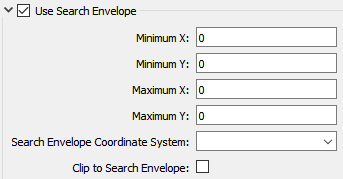
The parameters include the x and y coordinates of the bounding box as well as a parameter that defines the coordinate system.
How to Define the Bounding Box
Using the minimum and maximum x and y parameters, define a bounding box that will be used to filter the input features. Only features that intersect with the bounding box are returned. Note that the bounding box intersection is not a full geometry intersection (based on spatial relationships) that would be returned by a transformer like the SpatialFilter.
Note: If all four coordinates of the search envelope are left at 0, the search envelope will be disabled even if this option is checked.
Search Envelope Coordinate System
Specifies the coordinate system of the search envelope if it is different than the coordinate system of the data. The coordinate system associated with the data to be read must always be set if this parameter is set.
If this parameter is set, the minimum and maximum points of the search envelope are reprojected from the Search Envelope Coordinate System to the reader’s coordinate system prior to applying the envelope.
The underlying function for Use Search Envelope is an intersection; however, when Clip to Search Envelope is checked, a clipping operation is also performed.
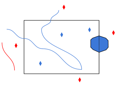
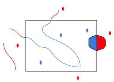
- When checked (set to Yes), this option instructs FME to clip features to the exact envelope boundary. FME removes any portions of imported features being read that are outside the search envelope.
- When left unchecked (set to No), features that overlap the boundary will be included in their full (unclipped) form.
|
Clip to Search Envelope: No |
Clip to Search Envelope: Yes |
|---|---|
|
Any features that cross the search envelope boundary will be read, including the portion that lies outside of the boundary.
|
Any features that cross the search envelope boundary will be clipped at the boundary, and only the portion that lies inside the boundary will be read.
|
|
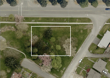
The search envelope includes the bounding box and the extent of the raster.
|
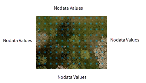
The search envelope includes only the area within the bounding box. The raster size will still match the bounding box, but the area without data will be filled with Nodata values to represent the absence of data, if the source raster has them. Raster Nodata may be a single value across all bands, a single value per band, or a separate alpha or transparency band that indicates the lack of data values (this is more common in images than other types of rasters).
|
Advanced
A GeoTIFF file stores projection parameters in a set of keys. A key has an ID number ranging from 0 to 65535.
When a GeoTIFF file contains pyramids (reduced-resolution images), this parameter specifies the pyramid level to read.
Pyramid level 0 represents the original raster data. Values greater than 0 represent a reduced-resolution image.
Note that the GeoTIFF format does not guarantee that the levels are ordered. For example, pyramid level 2 may have more rows or columns than pyramid level 1, or vice versa.
- When the value is set to Yes and the
ProjLinearUnitsInterpCorrectGeoKeyflag is present in the file, the coordinate system offsets will be assumed to be in the linear units of the projection. - When the value is set to No or the
ProjLinearUnitsInterpCorrectGeoKeyflag is not present, the Offsets in Coordinate System Units parameter is used to determine the interpretation of the coordinate system offsets.
- Yes: The coordinate system offsets stored in the GeoTIFF file will be interpreted as being in the linear units of the projection; this is correct according to the GeoTIFF specification.
- No: The coordinate system offsets will be interpreted as being in meters; this is what is actually done in practice by many software packages.
Note: If the offsets are explicitly marked as being in the coordinate system units (via the ProjLinearUnitsInterpCorrectGeoKey flag in the GeoTIFF dataset), and Prefer File Coordinate System Units is set to Yes, this option is ignored.
GeoTIFF contains a “raster type” key which specifies whether each pixel in the file represents an area (“PixelIsArea”) or a point (“PixelIsPoint”).
When reading PixelIsPoint data, by default, the raster extents is shifted up and left by half a pixel when transformed to the FME georeferencing model. Setting this value to Yes prevents this adjustment from happening.
