|
About Database Connections |
|---|
|
Database formats include a Database Connection parameter that defines and stores authentication information. For general information about sharing database connections, please see Using Database Connections. Note that Database Connection parameters differ slightly, depending on context and/or database format. |
|
Connection From the Connection parameter in a database format, you can do one of the following:
|
Database Connection
Connection File
This parameter identifies the pathname of a connection file to be used to connect to an Enterprise Geodatabase.
A connection file provides the necessary information to connect to the SDE server, such as the server name or the username.
The connection file must be a *.sde file and have the proper format for a connection file as defined by Esri. Connection files can be created in ArcCatalog.
Check this option to override the User and Password from the connection file. Overriding credentials is required for Connection Files that do not have saved credentials.
Note: This parameter is ignored if the Connection File is using OS Authentication.
Username and Password
Enter the username and password to access the service.
Constraints
After specifying the database connection, click the Browse button (...) to select tables for import. A connection window appears while the system retrieves the tables from the database.
Once the Select Tables dialog appears, you can select one or more tables. Click OK to dismiss the window and add the selected table name(s) to the Tables parameter.
When set to Features, the reader outputs features stored within tables.
When set to Metadata, provides the ability to read table-level metadata. In this mode, the reader outputs one feature per feature type. The geodb_type of the feature is geodb_metadata and the entire XML metadata document belonging to the Geodatabase table is found in the attribute geodb_metadata_string.
Where applicable, the following attributes are also supplied:
- fme_feature_identifier – Indicates the name of the object ID field,
- fme_contains_spatial_column – Indicates whether the table has a geometry column (or, in Esri ArcGIS terms, whether the table is a feature class)
- fme_geometry{0} – Indicates the types of geometry the feature class contains
- fme_dimension – Indicates whether the feature class is 2D or 3D.
If the table is a feature class, the geometry of the metadata feature returned is a polygon, representing the extents of the feature class, and the coordinate system of the feature class also gets set on the feature.
When reading metadata, the Feature Type parameters are used to determine which feature types should have metadata read from them.
Mosaic Parameters
A Mosaic Dataset is a collection of rasters that can be combined to produce a single raster image for viewing or analysis. This parameter provides options to combine the rasters to produce the desired result. They do not apply to raster datasets. The options are based on the mosaic options provided for mosaic datasets in ArcGIS. See Esri documentation for a more detailed explanation.
The following values are supported:
- None – Rasters will be ordered in the order they appear in the mosaic dataset catalog table.
- By Attribute – Rasters will be ordered by how close the value of the attribute given by Order Field is to the value supplied in Order Base Value.
- Closest to Center – Rasters are ordered by how close they are to the center of the combined image.
- Lock Raster – Only those rasters given in Lock Raster ID will be combined in the order listed
- North-west (default) – Rasters are ordered by how close they are to the north-west of the combined image.
- Seamline – Rasters will be combined using the existing seamlines.
When the value of Mosaic Method is set to By Attribute then this parameter specifies which field in the mosaic dataset’s attribute table will be used to compare values.
When the value of Mosaic Method is set to By Attribute then rasters will be ordered by how close the value of the field given by Order Field is to the value given in this parameter.
This parameter lists the ObjectIDs as a comma-separated list that will be used to give the order of the rasters when the value of Mosaic Method is set to Lock Raster.
Gives the option to reverse the order the rasters will be combined.
- Ascending – Those ordered first will be placed on top.
- Descending – Those ordered first will be placed on the bottom.
It is possible for more than one raster to overlap in any given area. The mosaic operator specifies how the cells in the overlapping area are combined:
- First – The cell from the first raster is chosen.
- Last – The cell from the last raster is chosen.
- Min – The cell with the smallest value is chosen.
- Max – The cell with the largest value is chosen.
- Mean – The average of all the cells is chosen.
- Blend – Overlapping cells will blended together based on a weight-based algorithm that uses the distance of the cells to the edge within the overlapping area.
- Sum – The total value of all the pixels added together from overlapping raster datasets.
Use this parameter to expose Format Attributes in Workbench when you create a workspace:
- In a dynamic scenario, it means these attributes can be passed to the output dataset at runtime.
- In a non-dynamic scenario, this parameter allows you to expose additional attributes on multiple feature types. Click the browse button to view the available format attributes (which are different for each format) for the reader.
A search envelope (also known as a bounding box) is a rectangular area that defines a geographic area. In FME, the easiest way to define a search envelope is to use search envelope parameters.
Defining a search envelope is the most efficient method of selecting an area of interest because FME will read only the data that is necessary – it does not have to read an entire dataset. Search Envelope parameters apply to both vector and raster datasets and can be particularly efficient if the source format has a spatial index.
Most FME readers have parameters to define the search envelope of data that is being read:
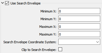
The parameters include the x and y coordinates of the bounding box as well as a parameter that defines the coordinate system.
How to Define the Bounding Box
Using the minimum and maximum x and y parameters, define a bounding box that will be used to filter the input features. Only features that intersect with the bounding box are returned. Note that the bounding box intersection is not a full geometry intersection (based on spatial relationships) that would be returned by a transformer like the SpatialFilter.
Note: If all four coordinates of the search envelope are left at 0, the search envelope will be disabled even if this option is checked.
Search Envelope Coordinate System
Specifies the coordinate system of the search envelope if it is different than the coordinate system of the data. The coordinate system associated with the data to be read must always be set if this parameter is set.
If this parameter is set, the minimum and maximum points of the search envelope are reprojected from the Search Envelope Coordinate System to the reader’s coordinate system prior to applying the envelope.
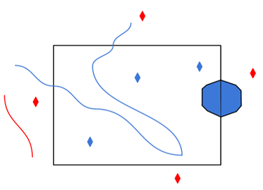
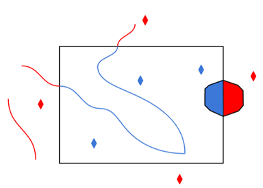
The underlying function for Use Search Envelope is an intersection; however, when Clip to Search Envelope is checked, a clipping operation is also performed.
- When checked (set to Yes), this option instructs FME to clip features to the exact envelope boundary. FME removes any portions of imported features being read that are outside the search envelope.
- When left unchecked (set to No), features that overlap the boundary will be included in their full (unclipped) form.
|
Clip to Search Envelope: No |
Clip to Search Envelope: Yes |
|---|---|
|
Any features that cross the search envelope boundary will be read, including the portion that lies outside of the boundary.
|
Any features that cross the search envelope boundary will be clipped at the boundary, and only the portion that lies inside the boundary will be read.
|
|
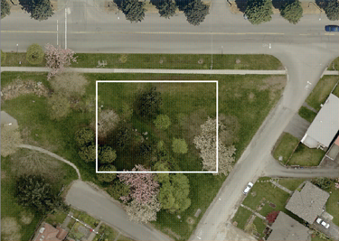
The search envelope includes the bounding box and the extent of the raster.
|
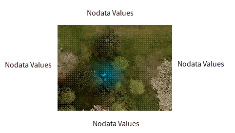
The search envelope includes only the area within the bounding box. The raster size will still match the bounding box, but the area without data will be filled with Nodata values to represent the absence of data, if the source raster has them. Raster Nodata may be a single value across all bands, a single value per band, or a separate alpha or transparency band that indicates the lack of data values (this is more common in images than other types of rasters).
|
Advanced
Specifies whether to create a connection to SDE that persists and can be shared by other SDE readers, writers, and transformers.
When set to Yes, the connection will remain open until FME shuts down, even if this reader is finished using it. Otherwise, the connection will be closed when the reader is shut down (unless another reader, writer, or transformer is still using the connection).
Creating a new connection is a resource-expensive operation. Depending on how FME is being used (for example, if there are multiple instances of the reader/writer being used), performance may improve by setting this parameter to Yes.
Managed rasters, rasters stored within the Geodatabase, represent Nodata as a bit mask on each band. This parameter specifies how to handle these Nodata bit masks.
- None – Nodata bit masks will be ignored
- Single Alpha Band (default) – Nodata bit masks for each band are merged into a single additional alpha band named geodb_nodata.
If merged into a single alpha band, then the alpha band will contain a value of 0 (Nodata) at a given cell if and only if the corresponding cell of all the other bands is Nodata.
This parameter only affects managed rasters. Unmanaged rasters, rasters stored in files outside the Geodatabase, have Nodata represented as a Nodata value per band and do not have Nodata bitmasks.
