Takes a set of topologically connected linework and creates topologically correct polygon features where the linework forms closed shapes.
Input Ports
The input lines must be topologically correct and must neither self-intersect nor intersect each other. They must close at their endpoints. If these conditions are met, any area features implied by the input lines are created. (In addition to the Snapping Pre-Processing Parameters, you can also use the Snapper, Intersector, and MRF2DCleaner to clean data that does not meet these conditions before it enters this transformer.) This transformer can also create polygons and donuts (holes/islands). Any lines that cannot be formed into polygons are joined together to create maximum length linestrings.
Output Ports
Contains the output polygons.
Contains any lines that did not close. If Create Donuts is checked, it also contains degenerate polygons.
Parameters
Group Processing
The default behavior is to use the entire set of input features as the group. This option allows you to select attributes that define which groups to form – each set of features that have the same value for all of these attributes will be processed as an independent group.
No attributes other than the Group By ones will be carried across from the Input features to the output features.
When All Features Received: This is the default behavior. Processing will only occur in this transformer once all input is present.
When Group Changes (Advanced): This transformer will process input groups in order. Changes of the value of the Group By parameter on the input stream will trigger processing on the currently accumulating group. This may improve overall speed (particularly with multiple, equally-sized groups), but could cause undesired behavior if input groups are not truly ordered.
There are two typical reasons for using When Group Changes (Advanced) . The first is incoming data that is intended to be processed in groups (and is already so ordered). In this case, the structure dictates Group By usage - not performance considerations.
The second possible reason is potential performance gains.
Performance gains are most likely when the data is already sorted (or read using a SQL ORDER BY statement) since less work is required of FME. If the data needs ordering, it can be sorted in the workspace (though the added processing overhead may negate any gains).
Sorting becomes more difficult according to the number of data streams. Multiple streams of data could be almost impossible to sort into the correct order, since all features matching a Group By value need to arrive before any features (of any feature type or dataset) belonging to the next group. In this case, using Group By with When All Features Received may be the equivalent and simpler approach.
Note: Multiple feature types and features from multiple datasets will not generally naturally occur in the correct order.
As with many scenarios, testing different approaches in your workspace with your data is the only definitive way to identify performance gains.
Polygon
Specifies whether curve endpoints must be connected in X,Y, and Z before being joined together (as opposed to just X, and Y). Note that if this is set to No, then the Connect in Z Mode parameter will specify how the Z values of segments that are not connected in 3D should be treated.
When viewed in 2D (ignoring Z), a path (which may define the border of a polygon) may appear to be closed as shown in the left figure below. This same path, when viewed in 3D, may appear to be open as shown in the right figure below.
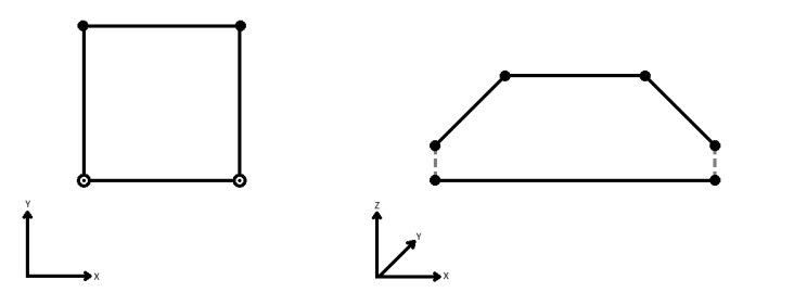
To specify how (and if) paths should be closed in 3D, select one of the listed modes.
| Mode | Description | Example |
|---|---|---|
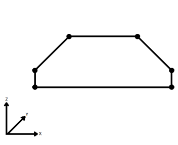
| Extend | The Curve is extended so that all vertices are left at their original location. |
|
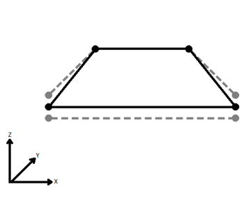
| Average | Subsequent vertices that are not connected, but share an x and a y value are combined into one vertex, whose Z value is the average of the original two. |
|
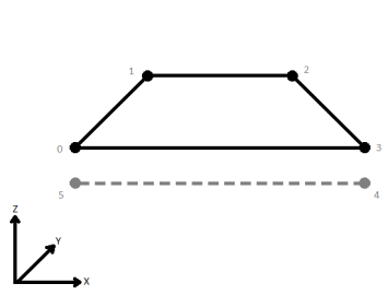
| First Wins | Subsequent vertices that are not connected, but share an x and a y value are combined into one vertex, whose Z value is taken from the first encountered vertex. |
|
| Last Wins | Subsequent vertices that are not connected, but share an x and a y value are combined into one vertex, whose Z value is taken from the last encountered vertex. |
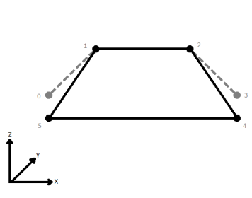
|
| Ignore | Z values are ignored. No change is made to the way the nodes are connected. |
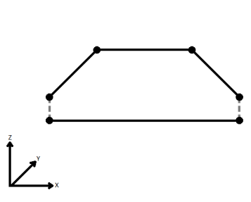
|
If set to Yes, then when lines originating from different input curves are concatenated into a longer curve in the output, they will be left as separate segments in a path. The default is No, which means that such lines will be joined into longer lines in the output unless they have different properties (for example, traits, measures, geometry name).
Specifies that coordinate "cycles" within a polygon are allowable and will be constructed; such polygons might be considered invalid by other parts of FME or by output formats. A "cycle" is a line segment that occurs twice in the same polygon's boundary (once in each direction).
Specifies if the direction of the input curves needs to be considered while building polygons. If set to Yes, only curves that are tip-to-tail will result in polygons, all others will be output through the “Incomplete” port.
Create Donuts
If checked, the resulting polygons will contain holes created by any other resulting polygons they completely contained. Following this, any holes that share a common edge will be dissolved together to make a larger hole.
If unchecked, the resulting polygons are output via the Area port. Note that if you want to create donut polygons, you will need to use the DonutBuilder.
Yes: Polygons that are holes of another polygon will not be output.
No: Polygons that are holes of another polygon will be output.
Attribute Accumulation
If Drop Incoming Attributes is chosen, the output feature will not preserve any input attributes. If Merge Incoming Attributes is chosen, the output feature will merge all input attributes. If Use Attributes From One Feature is chosen, the output feature will get attributes from only one input feature.
Generate List
When enabled, adds a list attribute to the output features, containing an element for each input feature which contributed to that geometry, in order of appearance.
This parameter can also be used to preserve attributes from input features.
Enter a name for the list attribute.
Note: List attributes are not accessible from the output schema in Workbench unless they are first processed using a transformer that operates on them, such as ListExploder or ListConcatenator. Alternatively, AttributeExposer can be used.
All Attributes: Every attribute from all input features that created an output feature will be added to the list specified in List Name.
Selected Attributes: Only the attributes specified in the Selected Attributes parameter will be added to the list specified in List Name.
The attributes to be added to the list when Add To List is Selected Attributes.
An optional attribute to include in the generated list, which indicates whether the direction of that input feature has been preserved (using same) or reversed (using opposite) in the output feature.
Snapping Pre-Processing Parameters
When this parameter is set to None, no snapping takes place.
When this parameter is set to End Point Snapping, the transformer:
- Snaps end points of lines together if their distances are within the specified tolerance.
When this parameter is set to Vertex Snapping, the transformer does the following:
- Snaps vertices of lines together if their distances are within the specified tolerance.
When two features are snapped together, the feature that entered the factory most recently is the one that is modified.
Snapping Tolerance specifies the distance, in ground units, that the snapping occurs between features.
Example
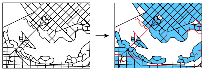
The example below illustrates a set of topologically connected linework on the left and the output of the AreaBuilder transformer on the right. In the output, the topologically correct polygons are highlighted in blue where the linework formed closed shapes, while the lines that did not close are shown in red.
Editing Transformer Parameters
Using a set of menu options, transformer parameters can be assigned by referencing other elements in the workspace. More advanced functions, such as an advanced editor and an arithmetic editor, are also available in some transformers. To access a menu of these options, click  beside the applicable parameter. For more information, see Transformer Parameter Menu Options.
Defining Values
There are several ways to define a value for use in a Transformer. The simplest is to simply type in a value or string, which can include functions of various types such as attribute references, math and string functions, and workspace parameters. There are a number of tools and shortcuts that can assist in constructing values, generally available from the drop-down context menu adjacent to the value field.
Using the Text Editor
The Text Editor provides a convenient way to construct text strings (including regular expressions) from various data sources, such as attributes, parameters, and constants, where the result is used directly inside a parameter.
Using the Arithmetic Editor
The Arithmetic Editor provides a convenient way to construct math expressions from various data sources, such as attributes, parameters, and feature functions, where the result is used directly inside a parameter.
Conditional Values
Set values depending on one or more test conditions that either pass or fail.
Parameter Condition Definition Dialog
Content
Expressions and strings can include a number of functions, characters, parameters, and more.
When setting values - whether entered directly in a parameter or constructed using one of the editors - strings and expressions containing String, Math, Date/Time or FME Feature Functions will have those functions evaluated. Therefore, the names of these functions (in the form @<function_name>) should not be used as literal string values.
| These functions manipulate and format strings. | |
|
Special Characters |
A set of control characters is available in the Text Editor. |
| Math functions are available in both editors. | |
| Date/Time Functions | Date and time functions are available in the Text Editor. |
| These operators are available in the Arithmetic Editor. | |
| These return primarily feature-specific values. | |
| FME and workspace-specific parameters may be used. | |
| Creating and Modifying User Parameters | Create your own editable parameters. |
Dialog Options - Tables
Transformers with table-style parameters have additional tools for populating and manipulating values.
|
Row Reordering
|
Enabled once you have clicked on a row item. Choices include:
|
|
Cut, Copy, and Paste
|
Enabled once you have clicked on a row item. Choices include:
Cut, copy, and paste may be used within a transformer, or between transformers. |
|
Filter
|
Start typing a string, and the matrix will only display rows matching those characters. Searches all columns. This only affects the display of attributes within the transformer - it does not alter which attributes are output. |
|
Import
|
Import populates the table with a set of new attributes read from a dataset. Specific application varies between transformers. |
|
Reset/Refresh
|
Generally resets the table to its initial state, and may provide additional options to remove invalid entries. Behavior varies between transformers. |
Note: Not all tools are available in all transformers.
FME Community
The FME Community is the place for demos, how-tos, articles, FAQs, and more. Get answers to your questions, learn from other users, and suggest, vote, and comment on new features.
Search for samples and information about this transformer on the FME Community.
Keywords: CAD fenceline island ring PolygonBuilder Polygonizer


