TOLERANCE
The TOLERANCE clause must be specified. This value serves as the default tolerance of the input features if the TOLERANCE_ATTR clause is not specified or the features have invalid tolerance value. The minimum value allowed is 0.0.
If the TOLERANCE_ATTR is specified and the value of the <attribute_name> is greater than or equal to 0.0, this value is used instead of the value specified in TOLERANCE clause.
SIMPLIFY
If the SIMPLIFY clause is set to “YES”, the line weeding / generalization will be included as part of the cleaning process. This involves the removal of line string vertices based on a specified tolerance. This process uses a weeding tolerance of the value of (FILTERFACTOR * TOLERANCE) or (FILTERFACTOR* value of TOLERANCE_ATTR). The latter is used whenever TOLERANCE_ATTR clause is specified and its value is valid. The larger the value of the weeding tolerance, the more vertices will be removed. The default value of FILTERFACTOR is 1.0.

FIGURE 1 Line string before and after simplification
SHORT_ELEMENT
If the SHORT_ELEMENT clause is set to “YES”, geometries of features that have lengths smaller than the specified tolerances are deleted. Short geometries created during the cleaning process are also deleted.
EXTEND
If the EXTEND clause is set to “YES”, the MRF Extend module is enabled. It is useful to extend certain elements – correcting for undershoot – while maintaining line-work direction. If a feature has a free end, this module will attempt to extend it until it meets other line-work within its tolerance; no intersections are created. This module does not process overshoots; the combination INTERSECTION and DANGLER modules can be used to serve this purpose.
The EXTEND clause processes elements in the following manner:
- line-line extension
- line-arc extension
- arc-arc extension
Line-line extension
In the figure below, lines AB and CD will be extended to point E, if E is within tolerance of both AB and CD, and both B and D are free ends.
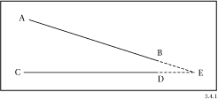
FIGURE 2 Linear extension, example 1
In Figure 3, lines AB and DE cannot be extended to point F, even though the distance BF is less than the tolerance for AB and EF is less than the tolerance for DE. This is because B is not a free end.
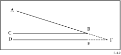
FIGURE 3 Linear extension, example 2
In Figure 4, CD has a tolerance layer larger than both the distances DE and CD. In this case, point D (rather than point C) will be extended to point E, since it has the smaller extension distance.
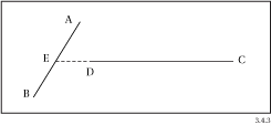
FIGURE 4 Linear extension, example 3
If a line can be extended to more than one element, it will be extended only as far as the closest one. In Figure 5, line AB will be extended to point C (not D or E).
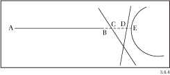
FIGURE 5 Linear extension, example 4
Line-Arc Extension
Figure 6 shows that circular arc AB will be extended along its path to point C, if BC is less than the tolerance for AB. Also, line DE will be extended to DEF if EF is less than DE’s tolerance.
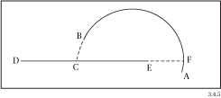
FIGURE 6 Line-arc extension, example 1
Arc-Arc Extension
Figure 7 shows that for arcs AB and DE, if BC is less than the tolerance for AB, then arc AB will be extended to C. Arc DE will be extended to F, if EF is less than the tolerance of DE.
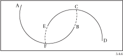
FIGURE 7 Arc-arc extension, example 1
INTERSECT
MRF Intersect flags and/or creates true and fuzzy intersections. It has element intersection, clustering, and splitting sub-functions.
MRF Intersect recognizes two types of relationships:
True intersections: When two vectors cross each other, the crossover point (X) is called a true intersection

Fuzzy intersections: A fuzzy intersection can be created from elements which are within
one of the tolerance distances, but do not actually touch or cross. In other words, the two
lines nearly intersect, and the minimum distance from the end of one line to the other line
is shorter than one of the lines’ tolerances

If the INTERSECT clause is set to “YES”, the MRF Intersect module is enabled. This module computes intersections between all input features, breaking arcs and lines wherever an intersection occurs. A fuzzy intersection is also created from geometries which are within one of the tolerance distances, but do not actually touch or cross.
If the FUZZY_INTERSECT clause is set to “NO” then fuzzy intersections will not be created in the process.
DUPLICATE_REMOVE
If the DUPLICATE_REMOVE clause is set to “YES”, the MRF Duplicate remover module is enabled. Features are considered to be duplicates if their geometries are within tolerance and only features with a smaller tolerance will remain after cleaning.
JOIN
If the JOIN clause is set to “YES”, then singly-connected features will be joined to form longer ones. A pair of linear features become candidates for joining only when the two of them are singly connected at a given node or end point.
CONFLATE
If the CONFLATE clause is set to “YES”, then the geometry of a feature can be changed match that of another, if the two are approximately the same to begin with.
DANGLER
A dangle is a geometry that has at least one free end point. If the DANGLER clause is set to “YES”, MRFCleanFactory will remove dangles if their lengths are less than the (DANGLEFACTOR * TOLERANCE) or (DANGLEFACTOR * value of TOLERANCE_ATTR). Again the latter is always used whenever possible. The default value of DANGLEFACTOR is 1.0.
See the MRFCleaner topics for a description of the other types of output clauses that are supported.
FME Community
The FME Community is the place for demos, how-tos, articles, FAQs, and more. Get answers to your questions, learn from other users, and suggest, vote, and comment on new features.
Search for samples and information about this transformer on the FME Community.