Entity Handling
- Yes: Forces all edges to be read in.
- Auto: The value of the SketchUp option View: Edge Style will determine whether edges are read in. This option is stored on the feature as the attribute RenderingOptions.EdgeDisplayMode.
- Standalone Only: Only edges that do not make up faces will be read in.
- No (default): Edges will not be read in.
- Yes: Instructs the reader to read all geometry elements, even if they are not displayed inside the SketchUp application. Geometry can be hidden with the visibility flag on the layer or on individual geometry elements
- Auto (default): The value of the SketchUp option View: Hidden Geometry will determine whether invisible Geometry and Layers are read in. This option is stored on the feature as the attribute RenderingOptions.DrawHidden.
- No: Only geometry elements that are visible will be read in.
Note: Layers that are not visible will still have a layer (feature type) exposed in the schema.
- Yes: This option instructs the reader to use the material associated with a geometry’s layer when creating its appearance. This option can be useful to visualize which layer each geometry is associated with. Entities associated with Layer 0 that are nested within a group will inherit that group’s layer material.
- Auto (default): The value of the SketchUp option Color by Layer will determine whether to use layer materials. This option is stored on the feature as the attribute RenderingOptions.DisplayColorByLayer.
- No: Appearances will be created using the material associated with each geometry.
Coordinate System
This parameter selects the datum that will be used to define the coordinate system of the SketchUp model. A datum can be chosen from the list, or entered manually.
Note: If the chosen datum is not valid, the default of WGS84 will be used.
If the value is Yes, the companion dataset files (having the same name as the primary file) are read in order to acquire the coordinate system and the data necessary to convert points to the world coordinate system.
In the absence of companion files with the same name as the primary file, FME looks in the same folder for files named global.*.
Schema Attributes
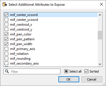
Use this parameter to expose Format Attributes in Workbench when you create a workspace:
- In a dynamic scenario, it means these attributes can be passed to the output dataset at runtime.
- In a non-dynamic scenario where you have multiple feature types, it is convenient to expose additional attributes using this one parameter. For example, if you have ten feature types and want to expose the same attribute in each one, it is easier to define it once than it is to set each feature type individually in the workspace.

Using the minimum and maximum x and y parameters, define a bounding box that will be used to filter the input features. Only features that intersect with the bounding box are returned.
If all four coordinates of the search envelope are specified as 0, the search envelope will be disabled.
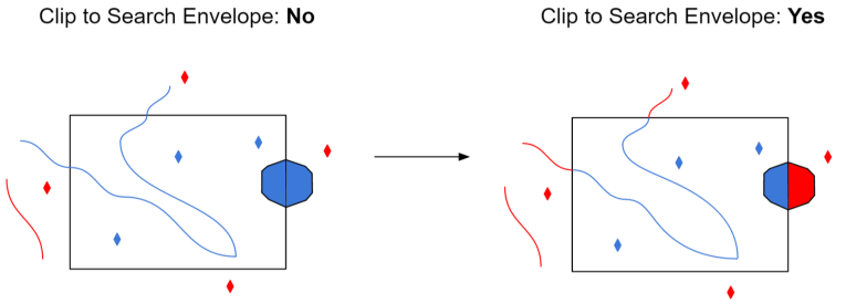
When selected, this parameter removes any portions of imported features being read that are outside the Search Envelope.
The example below illustrates the results of the Search Envelope when Clip to Search Envelope is not selected (set to No) and when it is selected (set to Yes).
- No: Any features that cross the search envelope boundary will be read, including the portion that lies outside of the boundary.
- Yes: Any features that cross the search envelope boundary will be clipped at the boundary, and only the portion that lies inside the boundary will be read. The underlying function for the Clip to Search Envelope function is an intersection; however, when Clip to Search Envelope is selected, a clipping operation is also performed in addition to the intersection.
