| Database Connections |
|---|
|
Connections store authentication information. For general information about sharing database connections, please see Using Database Connections. Note that different subsets of Database Connection parameters are made available in different contexts. Select an existing connection, or Add Database Connection to define a new connection. The new connection can be made visible only to the current user, or can be shared among multiple users. |
Database Connection
If a template Personal Geodatabase is specified, the destination Personal Geodatabase is replaced with a copy of the template before writing begins.
Constraints
Click this button to select tables for export. You must have a personal database to browse.
After you click the Browse button, a search window appears while the system compiles a table list from the database. Once the table list appears, you can select one or more tables, and then click the OK button to dismiss the window. The table name(s) will appear in the table list field in the Reader Parameters box.
Enter any SQL where clause that constrains the attributes of the layers selected in the layer list (for example, NUMLANES=2).
Specifies whether to only translate features that contain some kind of geometry.
Specifies whether or not to resolve the domain code found in feature classes and tables into the domain value.
This means that when an attribute of a feature has a coded value domain associated with it, another attribute will also be added that represents the textual description of the coded attribute. The new attribute will be <attribute-name>_resolved, where <attribute-name> is the name of the attribute containing the code.
Specifies whether or not to resolve the subtype field values found on feature classes and tables into the name of the actual subtype.
Note: You can speed up translations involving the Geodatabase Reader by not resolving subtypes and coded value domains. These operations add extra processing to each row of tables and feature classes that contain subtypes or coded value domains.
Specifies whether to read the network portion of network features. When checked, junctions will be read as points (geodb_point) and edges will be read as lines (geodb_polyline). Additionally, none of the network related attribution will be supplied on the features. Checking this option speeds up reading of network features significantly.
Determines whether to read relationship features present in a source dataset. When this parameter is checked, feature types containing simple relationships will be ignored, and feature types containing attributed relationships will be treated as non-spatial tables. When this parameter is unchecked, relationships will be read normally as either simple or attributed. The speed of reading features is vastly improved if relationships are ignored.
Determines whether complex edge features should be split. When split, complex edge features are read at the element level rather than the feature level. The element level represents the logical view of the geometric network. As a result, no network connectivity information is lost.
When split, each FME feature stores the following attributes:
|
Attribute Name |
Contents |
|---|---|
|
geodb_element_id |
The element ID of the logical edge element. |
|
geodb_element_index |
An attribute created and assigned by FME. It is used to order the edge elements within a complex feature. The index begins at 0, not 1. |
|
geodb_from_junction_element_id |
The junction element ID that corresponds to the from endpoint. Note: This is the from endpoint of the edge element, not the edge feature. |
|
geodb_to_junction_element_id |
The junction element ID that corresponds to the to endpoint. Note: This is the to endpoint of the edge element, not the edge feature. |
The following complex edge attributes are not present on the FME feature: geodb_junction_feature_count and geodb_edge_element_count. Even though elements are being read, the geodb_type of each feature is still geodb_complex_edge.
If an error occurs when retrieving the geometry for an edge element, then the geometry is skipped but the network attributes are still read.
Note: This parameter is not valid when reading relationship classes.
Specifies whether or not to split multi-part annotations into separate features for each "element" when reading. If checked, a single feature for each element (usually a word) in a multi-part annotation will be produced on reading, resulting in feature-specific attributes such as angle and text position being stored according to the location of each element. If left unchecked, multi-part annotations will be read normally, as a single feature storing a single set of attributes describing the positioning of the text.
Schema Attributes
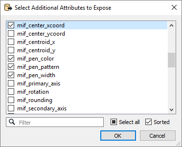
Use this parameter to expose Format Attributes in Workbench when you create a workspace:
- In a dynamic scenario, it means these attributes can be passed to the output dataset at runtime.
- In a non-dynamic scenario where you have multiple feature types, it is convenient to expose additional attributes using this one parameter. For example, if you have ten feature types and want to expose the same attribute in each one, it is easier to define it once than it is to set each feature type individually in the workspace.

This parameter controls how Geodatabase aliases are used.
- None: Aliases are ignored.
- Replace Attribute Names with Aliases: (Only applicable when adding a Reader.) Attributes on feature types will be named for their aliases rather than their official names. A geodb_feature_class_alias attribute will be included on each feature. Use this mode when the target format should create feature types using the aliases as attribute names.
- Expose Aliases as Metadata Attributes: For each attribute read, a second <name>_alias attribute will be added that stores the alias for the attribute in question. A geodb_feature_class_alias attribute will also be included on each feature. Use this mode when the target format is Geodatabase and the aliases should be preserved during feature class and table creation.
Using the minimum and maximum x and y parameters, define a bounding box that will be used to filter the input features. Only features that intersect with the bounding box are returned.
If all four coordinates of the search envelope are specified as 0, the search envelope will be disabled.
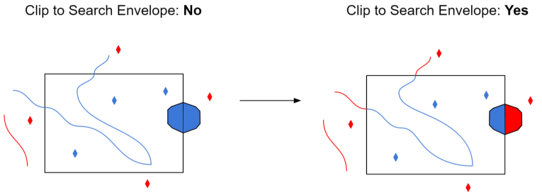
When selected, this parameter removes any portions of imported features being read that are outside the Search Envelope.
The example below illustrates the results of the Search Envelope when Clip to Search Envelope is not selected (set to No) and when it is selected (set to Yes).
- No: Any features that cross the search envelope boundary will be read, including the portion that lies outside of the boundary.
- Yes: Any features that cross the search envelope boundary will be clipped at the boundary, and only the portion that lies inside the boundary will be read. The underlying function for the Clip to Search Envelope function is an intersection; however, when Clip to Search Envelope is selected, a clipping operation is also performed in addition to the intersection.
