A face is a planar area in 3D space. The planar structure can be a polygon, an ellipse, or a donut (IFMEArea).
The orientation of an IFMEFace is determined by using the following rule - if the fingers of your right hand curl along the order of the vertices, the direction that the thumb points to is the front of the face. This thumb direction also describes the surface normal of the face, a vector that points outwards perpendicular from the area.
Contains: IFMEArea (1)
Contained by: IFMECompositeSurface, IFMEMultiSurface
A mesh is a special collection of simple single-sided facets or parts. These parts need not have any spatial or topological relationship between each other.
A mesh is referenced geometry containing a common vertex pool, vertex normal pool, and texture coordinate pool. The individual parts of the mesh represent single sided faces with planar polygon structure. The orientation of each mesh part is determined using the same rule as for faces. The parts of a mesh are defined by indices into the common pool. By allowing reuse of shared vertices, the physical representation size of a mesh can be smaller than an equivalent collection of surfaces.
A triangle strip is a series of connected triangular faces. These faces are defined by three consecutive points in a point list. The first three vertices (denoted below by v1, v2, and v3), define the first triangular face. A new triangle is formed by connecting the next point with its two immediate predecessors. That is, every additional point vi defines a new triangular face with vertices vi–2, vi–1, and vi.
For example, the second triangle is defined by v2, v3, v4, the third by v3, v4, v5, etc. The following diagram illustrates a typical IFMETriangleStrip.
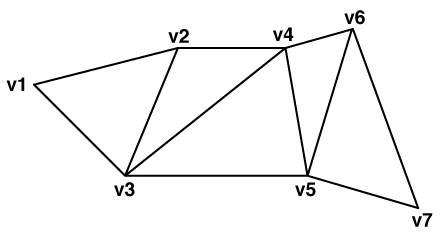
The orientation of the entire triangle strip is determined by the orientation of the first triangle. If the vertices of the first triangle are ordered counterclockwise then the front of the strip is displayed; otherwise the back is displayed. If the triangle strip has been flipped, then the front/back of the entire strip is actually the reverse of what the first triangle indicates.
A triangular fan is a series of connected triangular faces. The fan differs from a IFMETriangleStrip in the way how vertices define faces. The first three vertices (denoted below by v1, v2, and v3), define the first triangular face. A new triangle is formed by connecting the next point with its immediate predecessor and the first point of the triangle fan. That is, every additional point vi defines a new triangular face with vertices v1, vi-1, and vi.
For example, the second triangle is defined by v1, v3, v4, the third by v1, v4, v5, etc. The following diagram illustrates a typical IFMETriangleFan.
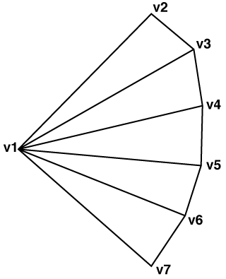
The orientation of the entire triangle fan is determined by the order of vertices of any triangle within the fan (all the triangles are already oriented in the same direction). When they are ordered counterclockwise the front is displayed; otherwise the back is displayed.
Contains: None
Contained by: IFMECompositeSurface, IFMEMultiSurface
A rectangular face is an optimized face representation that represents a face that is rectangular and that lies parallel on a coordinate plane (either xy-, xz-, or yz-plane).
This face specifies its position by using two points, the minimum corner and maximum corner. Because the face must lie parallel to a coordinate plane, the corner points share a common coordinate value. For example, if the rectangular face lies on the xy-plane, the corner points share a common z-value.
The surface normal of this rectangular face depends on the order of the specification of the min and max points, as described in the following table.
|
Plane to Which Rectangle is Parallel |
Order of Specification of (Coordinates of) the Corners |
Direction of the Surface Normal |
|
XY |
Min-corner, max-corner |
Positive Z-axis |
|
YZ |
Min-corner, max-corner |
Positive X-axis |
|
XZ |
Min-corner, max-corner |
Positive Y-axis |
|
XY |
Max-corner, min-corner |
Negative Z-axis |
|
YZ |
Max-corner, min-corner |
Negative X-axis |
|
XZ |
Max-corner, min-corner |
Negative Y-axis |
The surface normal determines the orientation of the rectangular face; that is, the direction in which the surface normal points indicates which side is the front.
With conjunction of a 4×4 transformation matrix, an IFMERectangleFace can be used to represent rectangular faces that are not parallel to the coordinate planes. This matrix can store affine transformations.
Contains: None
Contained by: IFMECompositeSurface, IFMEMultiSurface
A composite surface is a collection of connected surfaces. The components can be simple surfaces (faces, rectangular face, and triangular strip/fans), or other composite surfaces.
The orientation of the composite surface is determined by checking the orientation of the first surface.
The topological requirement of a composite surface is that the collection must represent a contiguous surface. It is also required that all members of the collection are oriented in a way consistent with its neighbors.
Contains: IFMESurface (0..n)
Contained by: IFMEBRepSolid, IFMECompositeSurface, IFMEMultiSurface
A multi-surface is a collection of surfaces. These surfaces need not have any spatial or topological relationship between each other.
Contains: IFMESurface (0..n)
Contained by: None