FME Transformers: 2026.2
Categories
Spatial Analysis
Related Transformers
3DSlicer
AreaOnAreaOverlayer
Bufferer
Intersector
LineOnAreaOverlayer
LineOnLineOverlayer
NeighborFinder
PointOnAreaOverlayer
PointOnLineOverlayer
PointOnPointOverlayer
Snipper
SpatialFilter
SpatialRelator
TopologyBuilder
Divides Candidate features using Clipper features, so that Candidates and parts of Candidates that are inside or outside of the Clipper features are output separately. Attributes may be shared between objects (spatial join).

Typical Uses
- Identifying where points, lines, or areas fall inside, outside, and intersect with one or more reference areas (Clippers), and modifying their geometry and attributes accordingly.
- Clipping features to perform calculations by Clipper area
- Clipping rasters or point clouds to a regular or irregular area of interest
- Clipping features to a map boundary for aesthetics
How does it work?
The Clipper takes in two sets of features:
- Clippers: Areas or solids which will be overlaid on Candidate features to identify which of those features fall inside or outside the Clippers. Those features are split where they cross the boundaries of the Clippers.
The geometry of the Clippers is unchanged, and they are discarded after use and not output from the Clipper transformer. - Candidates: Features with any type of geometry, which are compared to the Clippers, and split into multiple sections along the Clipper boundaries if necessary. Each section is output as either falling Inside or Outside the Clipper. They may also receive attributes from the Clippers (spatial join).
Candidate geometry is only altered if it intersects with a Clipper. If it falls wholly inside or outside the Clipper, it is designated as such and output with its geometry untouched.
Output features receive a Clipped Indicator attribute (default name _clipped), which is set to “yes” for features that have been segmented, identifying features that were wholly inside or outside the clip boundaries and those that intersected the Clipper boundaries and so were modified.
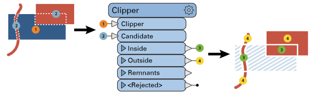
The Clipper works on all geometry types. This diagram illustrates area-on-line and area-on-area vector clipping results.
- (1) is a single area Clipper (in blue).
- (2) are the Candidates, a red line that crosses the Clipper (1), and red area that partially overlays the Clipper (1).
Both the line and area Candidates are split where they cross the Clipper boundary, and the results are output:
- (3) Portions of Candidates that fall Inside the Clipper (red only)
- (4) Portions of Candidates that fall Outside the Clipper (red only)
Raster Clipping, Alpha and Nodata
Raster cells are considered inside or outside the clipper based on either their centers or their boundaries, according to the Determine Cell Location By parameter.
If Raster Candidates > Add Alpha/Nodata is set to Yes, cells that fall outside the clip area but within the resulting bounding box will be assigned values as follows:
-
Bands with a Nodata value assigned: Nodata value
-
Bands without a Nodata value assigned:
-
RGB : Alpha band is added, all bands set to 0, resulting in transparent cells.
-
Bands with palettes: Nodata value is added, set to Nodata value.
-
Bands without palettes: Set to 0.
-
To set an explicit value for Nodata, use the RasterBandNodataSetter transformer prior to the Clipper.
This transformer is unaffected by raster band and palette selection.
Examples
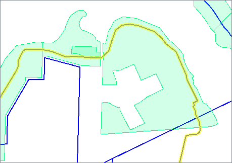
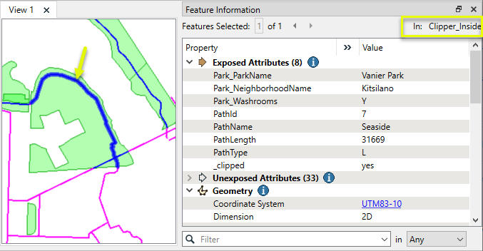
In this example, we start with two datasets - one with multiple park polygons, and the second with bike path lines. The bike paths run in and out of multiple parks, as can be seen here with the path selected and highlighted in yellow.
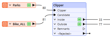
In the workspace, the parks are routed into the Clipper input port, and the bike paths are the Candidates - the features that will be altered according to the Clippers.
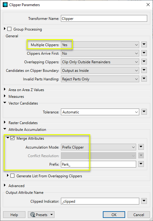
In the Clipper parameters dialog, Multiple Clippers is set to Yes, as we have multiple park polygons and want to clip the paths with all of them.
We enable Merge Attributes, which will transfer attributes from the parks (Clippers) to the lines (Candidates). By choosing Prefix Clipper, these new attributes will be prefixed with our string “Park_” and clearly indicate the source of the attribute.
The bike paths are split where they encounter a park boundary, receive attributes prefixed with Park_, and are output as either Inside or Outside feature types (shown here in blue and magenta).
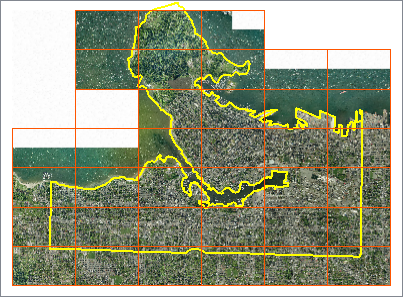
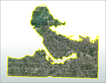
In this example, we have a series of orthophoto tiles, which we would like to clip to the city’s land boundary. The boundaries (extents) of each raster are overlaid in orange.
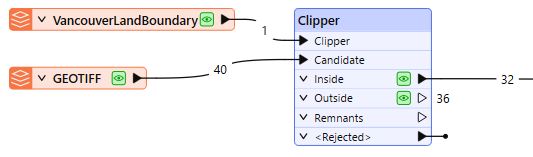
The boundary - a single polygon - is connected to the Clipper input port, and the series of TIFF images are connected to the Candidate port.
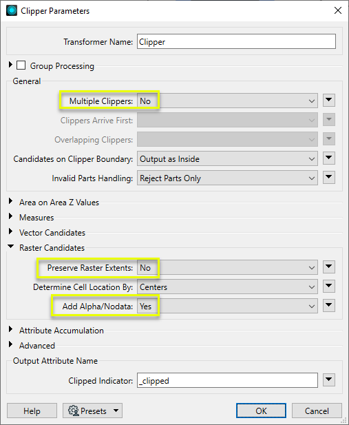
In the Clipper parameters dialog, Multiple Clippers is set to No, which will improve performance in this case, where we do have a single Clipper area.
For a raster clipping operation, the only other parameters we need to look at are Raster Candidates.
Setting Preserve Raster Extents to No will clip partial rasters as tightly as possible (while still maintaining a rectangular boundary). Add Alpha/Nodata as Yes will add a transparency layer where cells fall outside the irregular clip boundary but inside the raster extents.
Of the 40 rasters that went in, 32 of them fell partially or entirely Inside the clip boundary. In the rasters that intersected the boundary, cells that fall inside are untouched. Cells that fall outside have all bands set to 0 - including the added alpha band, indicating transparency.
This close-up shows the clipping of pixels along the water boundary.
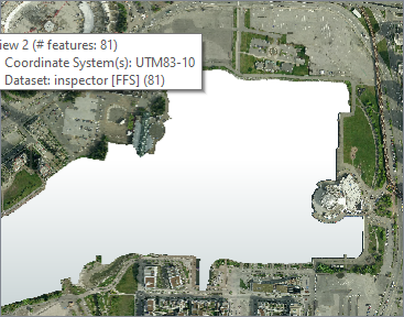
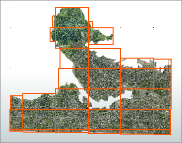
The extents of new rasters are shown here in orange. They are of varying size now, clipped tightly to the Clipper boundary (as we chose not to Preserve Raster Extents).
Usage Notes
-
Memory requirements: Clipping rasters can fail if not enough memory is available, which is more likely to happen the larger the raster is. If this occurs, increasing available memory or reducing raster resolution may help.
Choosing a Spatial Transformer
Many transformers can assess spatial relationships and perform spatial joins - analyzing topology, merging attributes, and sometimes modifying geometry. Generally, choosing the one that is most specific to the task you need to accomplish will provide the optimal performance results. If there is more than one way to do it (which is frequently the case), time spent on performance testing alternate methods may be worthwhile.
To correctly analyze spatial relationships, all features should be in the same coordinate system. The Reprojector may be useful for reprojecting features within the workspace.
|
Transformer |
Can Merge Attributes |
Alters Geometry |
Counts Related Features |
Creates List |
Supported Types* |
Recommended For |
|---|---|---|---|---|---|---|
| SpatialFilter | Yes | No | No | No |
|
|
| SpatialRelator | Yes | No | Yes | Yes |
|
|
| AreaOnAreaOverlayer | Yes | Yes | Yes | Yes |
|
|
| LineOnAreaOverlayer | Yes | Yes | Yes | Yes |
|
|
| LineOnLineOverlayer | Yes | Yes | Yes | Yes |
|
|
| PointOnAreaOverlayer | Yes | No | Yes | Yes |
|
|
| PointOnLineOverlayer | Yes | Yes | Yes | Yes |
|
|
| PointOnPointOverlayer | Yes | No | Yes | Yes |
|
|
| Intersector | Yes | Yes | Yes | Yes |
|
|
| Clipper | Yes | Yes | No | No |
|
|
| NeighborFinder | Yes | In some cases | No | Yes |
|
|
| TopologyBuilder | Yes | Yes | No | Yes |
|
|
* Note that Curve includes Lines, Arcs, and Paths. Area includes Polygons, Donuts, and Ellipses.
Spatial analysis can be processing-intensive, particularly when a large number of features are involved. If you would like to tune the performance of your workspace, this is a good place to start.
When there are multiple ways to configure a workspace to reach the same goal, it is often best to choose the transformer most specifically suited to your task.
If performance is an issue in your workspace, look for alternative methods, guided by geometry.
Configuration
Input Ports
The features routed into the transformer via the Clipper port identify the area against which all Candidate features are processed.
The Clipper can consist of any area (polygons, donuts, or aggregate/multi polygons/donuts) or solid (or multi-solid) geometries.
Any invalid clipping features that are encountered will be rejected.
Features to be clipped enter via the Candidate port.
Output Ports
Candidate features that are completely within the Clipper, and Candidate features that intersect the Clipper which were broken up into pieces. Those pieces that are on the inside of the Clipper are output via this port.
Candidate features completely outside of the Clipper are output via the Outside port, and Candidate features that intersect the Clipper which were broken up into pieces. Those pieces that are outside the clipping area are output via this port.
Candidates that are smaller than the automatic tolerance, and have been collapsed (area to line or point, line to point) will be output from this port.
Invalid Clipper features (that is, non-polygon features) as well as invalid Candidate features (that is, features with no geometry) are output via the <Rejected> port.
Rejected features will have an fme_rejection_code attribute with one of the following values:
EXTRA_CLIPPER_FEATURE
INVALID_CLIPPER_GEOMETRY_NOT_FINITE
INVALID_CLIPPER_GEOMETRY_NUMBER_OF_POINTS
INVALID_CLIPPER_GEOMETRY_NOT_FINITE
INVALID_CLIPPER_GEOMETRY_TYPE
INVALID_CLIPPER_GEOMETRY_UNPROCESSABLE_SOLID
INVALID_CANDIDATE_UNPROCESSABLE_CURVE
INVALID_CANDIDATE_UNPROCESSABLE_AREA
INVALID_CANDIDATE_UNPROCESSABLE_SURFACE
INVALID_CANDIDATE_UNPROCESSABLE_SOLID
INVALID_GEOMETRY_NOT_FINITE
INVALID_GEOMETRY_NUMBER_OF_POINTS
INVALID_GEOMETRY_NULL
INVALID_GEOMETRY_TYPE
Rejected Feature Handling: can be set to either terminate the translation or continue running when it encounters a rejected feature. This setting is available both as a default FME option and as a workspace parameter.
Parameters
|
Group By |
The default behavior is to use the entire set of features as the group. This option allows you to select attributes that define which groups to form. Note that when using Group By, if a Candidate has no equivalent Clipper, the feature is output unclipped via the Outside output port, with the attribute _fme_no_clipper = Yes. |
||||
|
Complete Groups |
Select the point in processing at which groups are processed:
There are two typical reasons for using When Group Changes (Advanced) . The first is incoming data that is intended to be processed in groups (and is already so ordered). In this case, the structure dictates Group By usage - not performance considerations. The second possible reason is potential performance gains. Performance gains are most likely when the data is already sorted (or read using a SQL ORDER BY statement) since less work is required of FME. If the data needs ordering, it can be sorted in the workspace (though the added processing overhead may negate any gains). Sorting becomes more difficult according to the number of data streams. Multiple streams of data could be almost impossible to sort into the correct order, since all features matching a Group By value need to arrive before any features (of any feature type or dataset) belonging to the next group. In this case, using Group By with When All Features Received may be the equivalent and simpler approach. Note Multiple feature types and features from multiple datasets will not generally naturally occur in the correct order.
As with many scenarios, testing different approaches in your workspace with your data is the only definitive way to identify performance gains. |
|
Multiple Clippers |
Yes: All Clipper features will be used. No: Only a single Clipper feature will be used. |
|
Clippers Arrive First |
Yes: The Clipper assumes that all Clipper features will enter the transformer before any Candidate features. Any further Clipper features that arrive after the first Candidate will be rejected. No: The Clipper makes no assumptions about the order of Candidates and Clippers features. Clippers are processed regardless of their relative order with Candidates. |
|
Overlapping Clippers |
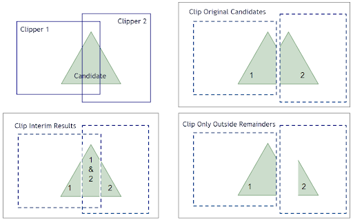
Controls how candidates get clipped when there are multiple clippers that overlap each other.
Clip Interim Results: Each clipper feature will clip the interim results (both inside and outside) produced by the previous clipper feature’s interaction with all the candidates. The part of a candidate that’s outside of all clippers will be output from the outside port. This option allows for each output piece to acquire the attributes from each of the Clipper features they were clipped by. Clip Original Candidates: Each clipper feature will clip the original form of a candidate. Their intersection will be output via the inside port. The part of a candidate that’s outside of all clippers will be output from the outside port. Clip Only Outside Remainders: Each candidate will be clipped by the first clipper, then the part that’s outside of the first clipper will be clipped by the second clipper, and so on. The part of a candidate that’s outside of all clippers will be output from the outside port. Note Because Clippers are applied to Candidates in the same order that they arrive at the factory, ordering Clippers by their likelihood to contain candidates may improve performance.
|
|
Candidates on Clipper Boundary |
This parameter directs what action should be taken with Candidate features that lie entirely on the boundary of the clipper. Output as Inside: The features that lie on the boundary are output via the Inside port. Output as Outside: The features that lie on the boundary are output via the Outside port. Output as Inside and Outside: The features that lie on the boundary are duplicated and output as both Inside and Outside. |
|
Invalid Parts Handling |
Reject Parts Only: Only parts in a multi/aggregate feature that are invalid as input (Clipper or Candidate) will be rejected. The rest of the feature will remain aggregated and continue to be processed. Feature hierarchy will be maintained with the rejected parts as much as possible. Reject Whole Feature: When a feature contains parts that are invalid as input (Clipper or Candidate), the whole feature will be rejected. |
|
Preserve Z From |
Specifies where to take the measures and Z values from when Clippers and Candidates are both areas. Candidate Only: All Z values of Clippers will be dropped. Clipper Only: All Z values from Candidates that intersect the Clippers will be dropped. Clipper and Candidate: Measures and Z values from the Candidate and Clipper are used. The Connect Z Mode parameter will determine how z values are handled. Note Clipper Z values and measures are not preserved when clipping curves (lines) with areas.
|
||||||||
|
Missing Z Values |
Specifies how to deal with geometries that have z values, but are missing at least one value. Planar Interpolation: Depending on the option selected for “Preserve Z From” parameter, input candidate or clipper areas are temporarily interpreted as surfaces, and Z values on new vertices are determined by interpolation using that temporary surface. Linear Interpolation: Use the Z values from adjacent vertices to perform a linear interpolation to determine the missing Z value Custom Value: Use the value specified in this parameter on any vertices with a missing Z value. None (Drop Values): If an output feature has missing Z values on any vertices, all Z values are dropped. If an output feature has Z values on all vertices, all Z values are preserved. |
||||||||
|
Connect Z Mode |
If applicable, select a method for handling z values. To specify how (and if) paths should be closed in 3D, select a mode.
|
|
Preserve Measures From |
Specifies where to take the measures from. Candidate Only: All measures of the Clippers will be dropped. Clipper Only: All measures from the Candidates that intersect the Candidate will be dropped. Clipper and Candidate: Measures from the Candidate and Clipper are used. Note Clipper measures are not preserved when clipping curves (lines) with areas.
|
|
Missing Measure Values |
Specifies how to deal with geometries that have measures, but are missing at least one value. Linear Interpolation: Use the measure values from adjacent vertices to perform a linear interpolation to determine the missing measure value. Neighboring Vertex: Copy the measure value from a neighboring vertex. Custom Value: Use the value specified in this parameter on any vertices with a missing measure value. None (Drop Values): If an output feature has missing measure values on any vertices, all measure values are dropped. If an output feature has measure values on all vertices, all measure values are preserved. |
|
Tolerance |
The minimum distance between geometries in 2D before they are considered equal, in ground units. If the tolerance is Automatic, a tolerance will be automatically computed based on the location of the input geometries. Additionally, a custom tolerance may be used. |
| Preserve Candidate Extents | If this parameter is set to No, the Inside rasters which were clipped will be equal to the intersections of the Clippers and Candidates. Otherwise, the intersections will be padded so that the extents are identical to those of the input rasters. |
|
Determine Cell Location By |
Bounds: Cells whose bounds are completely inside a clipper are considered “inside.” Cells whose bounds are completely outside a clipper are considered “outside.” Cells whose bounds are partially inside a clipper and partially outside a clipper are considered on the Clipper Boundary and will be output based on the Candidates on Clipper Boundary setting. Centers: Cells whose centers are inside a clipper are considered “inside.” Cells whose centers out outside a clipper are considered “outside.” Cells whose centers are on a Clipper Boundary will be output based on the Candidates on Clipper Boundary setting |
|
Add Alpha/Nodata |
If Yes, either an alpha band with transparency or Nodata values will be applied outside clip boundaries, as appropriate. |
Merge Attributes
When enabled, attributes on the Clipper will be merged onto the Candidate as defined by the parameters here. Otherwise, no attribute merging will take place.
If attributes on the Clipper and Candidate features share the same name, but are not geometry attributes that start with fme_, then they are deemed conflicted.
|
Accumulation Mode |
Merge Clipper: The Candidate feature will retain all of its own un-conflicted attributes, and will additionally acquire any un-conflicted attributes that the Clipper feature has. This mode will handle conflicted attributes based on the Conflict Resolution parameter. Prefix Clipper: The Candidate feature will retain all of its own attributes. In addition, the Candidate will acquire attributes reflecting the Clipper feature’s attributes, with the name prefixed with the Prefix parameter. Only Use Clipper: The Candidate feature will have all of its attributes removed, except geometry attributes that start with fme_. Then, all of the attributes from one (arbitrary) Clipper feature will be placed onto the Candidate. |
|
Conflict Resolution |
Use Candidate: If a conflict occurs, the Candidate values will be maintained. Use Clipper: If a conflict occurs, the values of the Clipper will be transferred onto the Candidate. |
|
Prefix |
If the Accumulation Mode parameter is set to Prefix Clipper, this value will prefix attributes that are being added to the Candidate feature from the Clipper feature. |
Generate List From Overlapping Clippers
When enabled, adds a list attribute to the output features, and the attributes of containing Clipper features are added to the list. Candidates will receive list attributes from all containing Clipper features.
|
Clipper List Name |
Enter a name for the list attribute. Note List attributes are not accessible from the output schema in FME Workbench until they are exposed with an AttributeExposer or processed with a transformer that operates on them, such as a ListExploder or ListConcatenator.
|
|
Add To List |
All Attributes: All attributes will be added to the output features. Selected Attributes: Enables the Selected Attributes parameter, where specific attributes may be chosen to be added. |
|
Selected Attributes |
Enabled when Add To List is set to Selected Attributes. Specify the attributes you wish to be added. |
|
Preserve Feature Order |
This parameter controls the order in which features exit a transformer. When a transformer has more than one output port, features usually exit one port at a time. At times, it may be useful to keep the order that features arrived in, switching from port to port as necessary. This allows feature order to be preserved, though at a potential cost in processing efficiency. Select a method for feature ordering.
|
|
Clipped Indicator |
Name the attribute to contain a value of yes on any features output via either the Inside or Outside port which were cut by the transformer, and a value of no on any output features which were not changed by the transformer. |
Editing Transformer Parameters
Transformer parameters can be set by directly entering values, using expressions, or referencing other elements in the workspace such as attribute values or user parameters. Various editors and context menus are available to assist. To see what is available, click  beside the applicable parameter.
Defining Values
There are several ways to define a value for use in a Transformer. The simplest is to simply type in a value or string, which can include functions of various types such as attribute references, math and string functions, and workspace parameters.
Using the Text Editor
The Text Editor provides a convenient way to construct text strings (including regular expressions) from various data sources, such as attributes, parameters, and constants, where the result is used directly inside a parameter.
Using the Arithmetic Editor
The Arithmetic Editor provides a convenient way to construct math expressions from various data sources, such as attributes, parameters, and feature functions, where the result is used directly inside a parameter.
Conditional Values
Set values depending on one or more test conditions that either pass or fail.
Parameter Condition Definition Dialog
Content
Expressions and strings can include a number of functions, characters, parameters, and more.
When setting values - whether entered directly in a parameter or constructed using one of the editors - strings and expressions containing String, Math, Date/Time or FME Feature Functions will have those functions evaluated. Therefore, the names of these functions (in the form @<function_name>) should not be used as literal string values.
| These functions manipulate and format strings. | |
|
Special Characters |
A set of control characters is available in the Text Editor. |
| Math functions are available in both editors. | |
| Date/Time Functions | Date and time functions are available in the Text Editor. |
| These operators are available in the Arithmetic Editor. | |
| These return primarily feature-specific values. | |
| FME and workspace-specific parameters may be used. | |
| Creating and Modifying User Parameters | Create your own editable parameters. |
Table Tools
Transformers with table-style parameters have additional tools for populating and manipulating values.
|
Row Reordering
|
Enabled once you have clicked on a row item. Choices include:
|
|
Cut, Copy, and Paste
|
Enabled once you have clicked on a row item. Choices include:
Cut, copy, and paste may be used within a transformer, or between transformers. |
|
Filter
|
Start typing a string, and the matrix will only display rows matching those characters. Searches all columns. This only affects the display of attributes within the transformer - it does not alter which attributes are output. |
|
Import
|
Import populates the table with a set of new attributes read from a dataset. Specific application varies between transformers. |
|
Reset/Refresh
|
Generally resets the table to its initial state, and may provide additional options to remove invalid entries. Behavior varies between transformers. |


Note: Not all tools are available in all transformers.
For more information, see Transformer Parameter Menu Options.
Reference
|
Processing Behavior |
|
|
Feature Holding |
Yes |
| Dependencies | |
| Aliases | 3DClipper PointCloudClipper RasterClipper SurfaceClipper |
| History |
FME Online Resources
The FME Community and Support Center Knowledge Base have a wealth of information, including active forums with 35,000+ members and thousands of articles.
Search for all results about the Clipper on the FME Community.
Examples may contain information licensed under the Open Government Licence – Vancouver, Open Government Licence - British Columbia, and/or Open Government Licence – Canada.