FME can read files in the Central European Normalisation (CEN) Standard format established by European Committee for Standardisation.
These help topics assume familiarity with this advanced format.
For the detailed format specification, please see:
https://www.iso.org/standard/54610.html
Writer Deprecation Notice
The GDF writer was deprecated in FME 2020.
Overview
The CEN standard for Geographic Data Files (GDF) is commonly called GDF 3.0. The International Standards Organization (ISO) standard is commonly called GDF 4.0. Several GDF data producers, like NAVTEQ and TeleAtlas, for example, do not strictly follow either GDF 3.0 or 4.0 standards, but rather follow their own slightly modified version of these standards.
GDF 3.0 (ASCII Sequential) is currently supported by FME (including variations such as NAVTEQ, TeleAtlas, and ETAK).
The original GDF specifications (GDF 3.0) were developed in Europe to meet the needs of professionals and organizations involved in the creation, update, supply and application of referenced and structured road network data.
It is much more than a generic GIS standard, as GDF gives rules on how to capture the data, as well as how the features, attributes and relationships are defined.
GDF was developed in a European project named EDRM (European Digital Road Map). Its primary use is for car navigation systems (for example, Bosch , Philips, Volvo); however, because the standard is based on a general, non-application-specific data model, it is also used for many other transport and traffic applications including Fleet Management, Dispatch Management, Traffic Analysis, Traffic Management, and Automatic Vehicle Locations.
The GDF file format is often referred to as a database, and was never intended to be used by applications directly. Indeed, the structure of GDF files themselves impose significant inefficiencies when extracting data from GDF files. GDF users will generally transform the data into some other database or format upon which their application will work directly.
In the GDF file structure, features (or elements) are organized into three layers. Features in each layer do not actually contain any geometry, but simply link to features in the layer below from which you are supposed to take the geometry.
- Level 0 (Topology): This level contains elementary GIS topology components. No features overlap in any way, and neighboring relationships are known. Everything is described by Nodes, Edges and Faces.
- Level 1 (Features): Level 1 is the most used level of GDF. It contains simple features like road elements, rivers, boundaries, and signposts. Features can have attributes that are specific to the feature (for example, one way, width of the road, number of lanes). Features can also have relations, which are very important for car navigation systems. For example, relations can include “forbidden turn from road element 1 to road element 2” or “road element 1 has priority over road element 2.”
- Level 2 (Complex Features): At this level, the level 1 “simple features” are aggregated to a higher level feature. For example, at level 1, all road elements of an intersection are represented. At level 2, the intersection may only be represented with a single point. The figure below illustrates this.
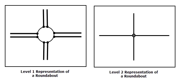
Roundabout Representation: Levels 1 and 2
Level 2 is of interest mostly when a simplified description of the road network is sufficient. For instance, inter-urban route calculation does not require a high level of detail. Vehicle location by means of a GPS receiver, however, does need the more detailed description of the road network.
The GDF reader uses symbolic names for different feature types stored within a data file. Each feature will have a gdf_type attribute on it.
| gdf_type | Description |
|---|---|
|
gdf_level_0_point |
These are point features found on level 0. |
|
gdf_level_0_line |
These are linear features found on level 0. |
|
gdf_level_0_polygon |
These are polygonal features found on level 0. |
|
gdf_level_1_point |
These are point features found on level 1. |
|
gdf_level_1_line |
These are linear features found on level 1. |
|
gdf_level_1_polygon |
These are polygonal features found on level 1. |
|
gdf_level_2_point |
These are (complex) point features found on level 2. |
|
gdf_level_2_line |
These are (complex) linear features found on level 2. |
|
gdf_level_2_polygon |
These are (complex) polygonal features found on level 2. |
|
gdf_nullrec |
Refer to the official GDF specification for NULLREC records for a full explanation of this feature type. |
|
gdf_volhdrec |
Refer to the official GDF specification for VOLHDREC records for a full explanation of this feature type. |
|
gdf_volhdrec_link_daset_vol |
This feature type holds mappings between gdf_volhdrec features and their dataset volumes. |
|
gdf_dshdrec_01 |
Refer to the official GDF specification for DSHDREC records for a full explanation of this feature type. |
|
gdf_dshdrec_01_link_language |
This feature type holds mappings between gdf_dshdrec_01 features and their languages. |
|
gdf_dshdrec_01_link_country |
This feature type holds mappings between gdf_dshdrec_01 features and their countries. |
|
gdf_dshdrec_02 gdf_dshdrec_03 gdf_dshdrec_04 gdf_dshdrec_05 gdf_dshdrec_06 gdf_dshdrec_07 |
Refer to the official GDF specification for DSHDREC records for a full explanation of these feature types. |
|
gdf_fieldefrec |
Refer to the official GDF specification for FIELDEFREC records for a full explanation of this feature type. |
|
gdf_recdefrec |
Refer to the official GDF specification for RECDEFREC records for a full explanation of this feature type. |
|
gdf_recdefrec_link_fld_name |
This feature type holds mappings between gdf_recdefrec features and their field names. |
|
gdf_atdefrec |
Refer to the official GDF specification for ATDEFREC records for a full explanation of this feature type. |
|
gdf_direc |
Refer to the official GDF specification for DIREC records for a full explanation of this feature type. |
|
gdf_featdefrec |
Refer to the official GDF specification for FEATDEFREC records for a full explanation of this feature type. |
|
gdf_spadorec |
Refer to the official GDF specification for SPADOREC records for a full explanation of this feature type. |
|
gdf_feaqualrec |
Refer to the official GDF specification for FEAQUALREC records for a full explanation of this feature type. |
|
gdf_atqualrec |
Refer to the official GDF specification for ATQUALREC records for a full explanation of this feature type. |
|
gdf_srcerec_01 gdf_srcerec_02 |
Refer to the official GDF specification for SRCEREC records for a full explanation of this feature type. |
|
gdf_srcerec_02_link_language |
This feature type holds mappings between gdf_srcerec_02 features and their languages. |
|
gdf_srcerec_02_link_country |
This feature type holds mappings between gdf_srcerec_02 features and their countries. |
|
gdf_srcerec_03 gdf_srcerec_04 gdf_srcerec_05 gdf_srcerec_06 gdf_srcerec_07 gdf_srcerec_08 gdf_srcerec_09 |
Refer to the official GDF specification for SRCEREC records for a full explanation of these feature types. |
|
gdf_dattvalrec |
Refer to the official GDF specification for DATTVALREC records for a full explanation of this feature type. |
|
gdf_sechrec_01 gdf_sechrec_02 gdf_sechrec_03 |
Refer to the official GDF specification for SECHREC records for a full explanation of this feature type. |
|
gdf_sechrec_03_link_feature_ |
This feature type holds mappings between gdf_sechrec_03 features and their feature qualities. |
|
gdf_sechrec_03_link_ |
This feature type holds mappings between gdf_sechrec_03 features and their attribute qualities. |
|
gdf_sechrec_04 |
Refer to the official GDF specification for SECHREC records for a full explanation of this feature type. |
|
gdf_sechrec_04_link_ |
This feature type holds mappings between gdf_sechrec_04 features and their source descriptions. |
|
gdf_sechrec_05 |
Refer to the official GDF specification for SECHREC records for a full explanation of this feature type. |
|
gdf_sechrec_05_link_ |
This feature type holds mappings between gdf_sechrec_05 features and their declinations. |
|
gdf_sechrec_06 |
Refer to the official GDF specification for SECHREC records for a full explanation of this feature type. |
|
gdf_sechrec_06_link_geoid |
This feature type holds mappings between gdf_sechrec_06 features and their geoids. |
|
gdf_sechrec_07 gdf_sechrec_08 gdf_sechrec_09 |
Refer to the official GDF specification for SECHREC records for a full explanation of this feature type. |
|
gdf_layhrec |
Refer to the official GDF specification for LAYHREC records for a full explanation of this feature type. |
|
gdf_layhrec_link_them_cod |
This feature type holds mappings between gdf_layhrec features and their theme codes. |
|
gdf_datelrec |
Refer to the official GDF specification for DATELREC records for a full explanation of this feature type. |
|
gdf_verdatrec |
Refer to the official GDF specification for VERDATREC records for a full explanation of this feature type. |
|
gdf_verdatrec_link_level |
This feature type holds mappings between gdf_verdatrec features and their levels. |
|
gdf_projecrec |
Refer to the official GDF specification for PROJECREC records for a full explanation of this feature type. |
|
gdf_projecrec_link_parms |
This feature type holds mappings between gdf_projecrec features and their projection parameters. |
|
gdf_natgridrec |
Refer to the official GDF specification for NATGRIDREC records for a full explanation of this feature type. |
|
gdf_geoidrec |
Refer to the official GDF specification for GEOIDREC records for a full explanation of this feature type. |
|
gdf_magnetrec |
Refer to the official GDF specification for MAGNETREC records for a full explanation of this feature type. |
|
gdf_commentrec |
Refer to the official GDF specification for COMMENTREC records for a full explanation of this feature type. |
|
gdf_voltermrec |
Refer to the official GDF specification for VOLTERMREC records for a full explanation of this feature type. |
|
gdf_xyzrec_point gdf_xyzrec_line |
Refer to the official GDF specification for XYZREC records for a full explanation of this feature type. |
|
gdf_nedgerec |
Refer to the official GDF specification for NEDGEREC records for a full explanation of this feature type. |
|
gdf_knotrec |
Refer to the official GDF specification for KNOTREC records for a full explanation of this feature type. |
|
gdf_facerec |
Refer to the official GDF specification for FACEREC records for a full explanation of this feature type. |
|
gdf_facerec_link_edge_id |
This feature type holds mappings between gdf_facerec features and their edge IDs. |
|
gdf_namerec |
Refer to the official GDF specification for NAMEREC records for a full explanation of this feature type. |
|
gdf_dsatrec |
Refer to the official GDF specification for DSATREC records for a full explanation of this feature type. |
|
gdf_dsatrec_link_attr |
This feature type holds mappings between gdf_dsatrec features and their attribute IDs. |
|
gdf_timerec |
Refer to the official GDF specification for TIMEREC records for a full explanation of this feature type. |
|
gdf_convertrec |
Refer to the official GDF specification for CONVERTREC records for a full explanation of this feature type. |
|
gdf_relatrec |
Refer to the official GDF specification for RELATREC records for a full explanation of this feature type. |
|
gdf_relatrec_link_feat |
This feature type holds mappings between gdf_relatrec features and their feature IDs. |
|
gdf_relatrec_link_attribute |
This feature type holds mappings between gdf_relatrec features and their attribute IDs. |
|
gdf_poferec |
Refer to the official GDF specification for POFEREC records for a full explanation of this feature type. |
|
gdf_poferec_link_knot |
This feature type holds mappings between gdf_poferec features and their knot IDs. |
|
gdf_poferec_link_attribute |
This feature type holds mappings between gdf_poferec features and their attribute IDs. |
|
gdf_linfrec |
Refer to the official GDF specification for LINFREC records for a full explanation of this feature type. |
|
gdf_linfrec_link_edge |
This feature type holds mappings between gdf_linfrec features and their edge IDs. |
|
gdf_linfrec_link_attribute |
This feature type holds mappings between gdf_linfrec features and their attribute IDs. |
|
gdf_arferec |
Refer to the official GDF specification for ARFEREC records for a full explanation of this feature type. |
|
gdf_arferec_link_face |
This feature type holds mappings between gdf_arferec features and their face IDs. |
|
gdf_arferec_link_attribute |
This feature type holds mappings between gdf_arferec features and their attribute IDs. |
|
gdf_compferec |
Refer to the official GDF specification for COMPFEREC records for a full explanation of this feature type. |
|
gdf_compferec_link_feat |
This feature type holds mappings between gdf_compferec features and their feature IDs. |
|
gdf_compferec_link_attribute |
This feature type holds mappings between gdf_compferec features and their attribute IDs. |
|
gdf_unknown_record |
All GDF records which are not completely understood by FME are output as this feature type. |
We used to have as a gdf_type every record type in addition to the geometric types. To make the geometry gdf_type more explicit, we now give a gdf_no_geom type to every feature type that does not contain any geometry, such as VOLHDREC.
Reader Overview
The GDF reader reads the entire file sequentially. Header information from the Volume level is therefore processed first, followed by information from the Dataset, Section, and Layer levels, respectively. Scaling and offset factors found in the header of the GDF file are applied to all coordinates read from the file. The reader extracts each individual feature, one at a time, and passes it on to the rest of FME for processing.
The reader supports a dynamic schema configuration based on the FIELDEFREC (03) and RECDEFREC (04) records. The reader has a default configuration for different variants such as Navteq and TeleAtlas 3.4. If the dataset to be read has a header with FIELDEFREC (03) and RECDEFREC (04) records, those will be used to adjust the configuration. Therefore, new record types can be defined in the dataset header and the reader will handle them correctly.
The geometry of level 1 points is the center of the bounding box of all the components. The geometry of level 1 lines is the concatenation of all the components. The geometry of level 1 areas is computed by "dissolving" of all the components.
Complex (Level 2) features symbolize abstract network topology and therefore cannot be faithfully represented by visual graphic representation in all cases. The attributes on complex features will always retain all information necessary to completely reconstruct the level 2 topology or otherwise access every aspect of the data represented in the GDF file. The geometry on complex features is intelligently created to visually represent those parts of the network topology where possible. In most cases, the geometry on complex features is indeed helpful in understanding the network through a graphical viewer.
The geometry assigned to complex features is either lines, points, or polygons. Complex features that have FROM/TO links are read as level 2 lines whose geometry is assumed to be a single segment line from the center of the bounding box of the FROM feature and to the center of the bounding box of the TO feature. If the complex feature has no FROM/TO links, then the types of the members are considered. Those with only polygonal members are read as level 2 polygons whose geometry is the result of dissolving all the polygonal members. Finally, those complex features that do not consist entirely of polygonal members are read as level 2 points whose geometry is assumed to be the center of the bounding box of all the components. One exception to the above should be noted; all complex features with no FROM/TO links and exactly one member will assume the complete geometry and type of that member. Any complex features that contain a reference to a member that does not appear in the file will be output as a COMPFEREC feature with no geometry.
When the GDF reader encounters an record type it does not know how to process, it simply outputs this element as an UNKNOWN_RECORD and moves on to read the next feature. However, this should not happen unless the record schema has not been previously defined in a RECDEFREC (04) record in the header.
In addition to the different record types, which are known as the physical representation in GDF terminology, the reader also takes into account the Data Model to create the FME features. This Data Model is vendor- and version-specific and defines the GDF feature names, and attribute names and values. Should the need arise, the Data Model for the different variants and versions of GDF can be edited in a text editor. The Data Model is in the FME install folder under plugins/gdf/DataModel.