RubberSheeter
Performs warping operations on the spatial coordinates of features. Using inverse distance weighting, RubberSheeter adjusts a set of observed features so they more closely match
some set of reference features. This transformer applies a different transformation
to each Observed vertex, depending
on its distance to nearby Control
vectors. It produces good corrections when the distortions in the Observed data are not constant.
Input Features
Two sets of features must be routed into this transformer:
- Features
that enter through the Control port
represent the control features used to compute the corrections.
- Features
that enter through the Observed port
are the features that will be corrected.
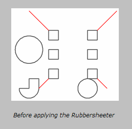
Each Control feature represents
a control vector whose start point is at some location in the original
Observed data space, and whose
end point is at the corresponding location in the desired output data
space. The control vector represents the correction required to go from
the observed vertex to the desired vertex. (Control vectors with only
one point are interpreted as a requirement that this location not change
from the observed dataset to the reference dataset. This is often referred
to as a tie point.)
Optionally, lines may be input as Constraint features to this transformer. These lines will be treated as boundaries, across which control vectors will have no influence on points of observed features. If the "line of sight" from a point on an Observed feature to the starting point of a Control vector crosses a Constraint line, that control vector will not affect the resulting warped position of the point in question. If the line of sight touches the end of a Constraint line, or either the Control vector or Observed point is actually located on the Constraint line, then the Control vector will still influence the observed point.
Note: This transformer does not currently support raster geometry.
Output Ports
The modified Observed features
are output via the Corrected
port.
Parameters
Transformer
 Group By
The default behavior is to use the entire set of input features as the group. This option allows you to select attributes that define which groups to form. Each set of features that have the same value for all of these attributes will be processed as an independent group.
 Group By Mode
Process At End (Blocking): This is the default behavior. Processing will only occur in this transformer once all input is present.
Process When Group Changes (Advanced): This transformer will process input groups in order. Changes of the value of the Group By parameter on the input stream will trigger processing on the currently accumulating group. This may improve overall speed (particularly with multiple, equally-sized groups), but could cause undesired behavior if input groups are not truly ordered.
 Considerations for Using Group By
There are two typical reasons for using Process When Group Changes (Advanced) . The first is incoming data that is intended to be processed in groups (and is already so ordered). In this case, the structure dictates Group By usage - not performance considerations.
The second possible reason is potential performance gains.
Performance gains are most likely when the data is already sorted (or read using a SQL ORDER BY statement) since less work is required of FME. If the data needs ordering, it can be sorted in the workspace (though the added processing overhead may negate any gains).
Sorting becomes more difficult according to the number of data streams. Multiple streams of data could be almost impossible to sort into the correct order, since all features matching a Group By value need to arrive before any features (of any feature type or dataset) belonging to the next group. In this case, using Group By with Process At End (Blocking) may be the equivalent and simpler approach.
Note: Multiple feature types and features from multiple datasets will not generally naturally occur in the correct order.
As with many scenarios, testing different approaches in your workspace with your data is the only definitive way to identify performance gains.
Parameters
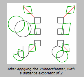
 Distance Exponent
Specifies how the strength of a correction will be affected
by its distance from an observed point. A value of 2 will cause the strength
to be decreased proportional to the square of the distance.
 Max Distance
Indicates the influence
of control vectors. Any control vector start point farther than the specified
distance from the point being operated on will have no effect in the correction
computation. If Max Distance is not specified (or is 0), then all control
vectors will be used for correcting every point.
 Max Number of Influencing Vectors
Indicates that only the closest given number of vectors will have an effect
on any point being warped. If not specified (or if 0), then all control
vectors will be used for correcting every point.
Comparison to the AffineWarper
The AffineWarper
transformer provides similar functionality but computes an affine (scale,
rotation, and offset) transformation based on Control
vector features and applies this transformation to the Observed features to generate output.
This makes the AffineWarper
more appropriate for cases when the entire set of Observed
data requires a single transformation.
Case Study
Click here to read how FME’s RubberSheeter was
used to combine Manukau City Council’s existing parcel-dependent cadastral
data with a newer “survey accurate” national digital cadastre.
Common Questions
I have a line feature only some of whose points fall inside the Max
Distance. How will it be warped? Only vertex points that lie inside
the Max Distance will get warped. Therefore, part of your line will be
warped, part of it will not.
Why doesn't FME warp the entire feature when one of its points falls
inside the Max Distance? Because this could causes topological networks
to become broken. Working on a point-by-point basis, connections will
never be broken because the common point on the connecting feature will
also get warped (even if the rest of that feature doesn't).
Example


Editing Transformer Parameters
Using a set of menu options, transformer parameters can be assigned by referencing other elements in the workspace. More advanced functions, such as an advanced editor and an arithmetic editor, are also available in some transformers. To access a menu of these options, click  beside the applicable parameter. For more information, see Transformer Parameter Menu Options.
Transformer Categories
Coordinates
Geometries
FME Licensing Level
FME Professional edition and above
Technical History
Associated FME function or factory: WarpFactory
Search FME Community
Search for samples and information about this transformer on the FME Community.


 beside the applicable parameter. For more information, see