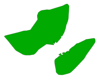
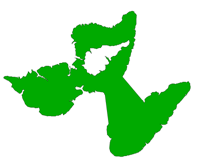
The AreaAmalgamator accepts polygonal geometries – including donuts – as input, and produces triangles that join input features into connected pieces, or amalgams. Small holes are removed at the end of this process.
The strategy for generalizing polygonal geometries is as follows:
- Redirect non-polygonal geometries onto the Invalid port.
- Dissolve the input polygonal geometries to remove shared boundaries and overlapping regions.
- Densify the dissolved polygonal geometries.
- Determine the convex hull of the densified polygonal geometries.
- Overlay the convex hull against the densified polygonal geometries to compute empty regions between the polygonal geometries.
- Triangulate the empty regions. Keep only triangles that are sufficiently short in length – those that satisfy the Maximum Triangle Length parameter.
- Dissolve the triangles to form connectors.
- For each connector, check to see if it is valid. It is valid if it shares a boundary with a dissolved polygonal geometry.
- Output all features not touched by any connectors to the Untouched port.
- Dissolve valid connectors with dissolved polygonal geometries to form amalgams.
- For each amalgam, remove small holes that do not satisfy the Minimum Hole Area parameter. Remaining (large) holes are output to the Holes port.
- For each amalgam, find all triangles that formed a part of its connectors. Output these triangles to the Triangles port.
- Output all amalgams to the Amalgamated port.
- For attribute behavior, please see List Name and ID Attribute in the Parameters section.
Input Ports
Polygonal geometries, including donuts. The polygonal geometries may overlap and share boundaries. However, each geometry should be valid (that is, not self-intersecting or non-planar).
Output Ports
Amalgams computed from input polygonal geometries.
Input polygonal geometries that are not touched by valid triangle connectors.
Holes in the amalgams whose areas exceed the Minimum Hole Area parameter.
Triangles that form the valid connectors joining input polygonal geometries.
Non-polygonal input. Occasionally, if an unexpected condition is met, some invalid intermediate results will be posted to this port.
| Input | Output |
|---|---|

|
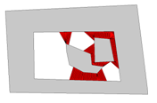
Triangles (red) |

|

Amalgamated (green) |

|

Holes (black) |
Parameters
Transformer
By specifying one or more Group By attributes, the input polygonal features will be partitioned into groups and the amalgamation process will be executed separately on each group. Within each group, all features will have the same values for the selected Group By attributes.
If no Group By attributes are selected, a single group will be formed containing all input polygonal features. By default, no Group By attributes are selected.
Process At End (Blocking): This is the default behavior. Processing will only occur in this transformer once all input is present.
Process When Group Changes (Advanced): This transformer will process input groups in order. Changes of the value of the Group By parameter on the input stream will trigger processing on the currently accumulating group. This may improve overall speed (particularly with multiple, equally-sized groups), but could cause undesired behavior if input groups are not truly ordered.
There are two typical reasons for using Process When Group Changes (Advanced) . The first is incoming data that is intended to be processed in groups (and is already so ordered). In this case, the structure dictates Group By usage - not performance considerations.
The second possible reason is potential performance gains.
Performance gains are most likely when the data is already sorted (or read using a SQL ORDER BY statement) since less work is required of FME. If the data needs ordering, it can be sorted in the workspace (though the added processing overhead may negate any gains).
Sorting becomes more difficult according to the number of data streams. Multiple streams of data could be almost impossible to sort into the correct order, since all features matching a Group By value need to arrive before any features (of any feature type or dataset) belonging to the next group. In this case, using Group By with Process At End (Blocking) may be the equivalent and simpler approach.
Note: Multiple feature types and features from multiple datasets will not generally naturally occur in the correct order.
As with many scenarios, testing different approaches in your workspace with your data is the only definitive way to identify performance gains.
Parameters
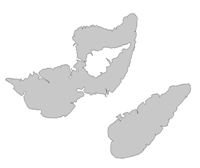
This parameter controls the mode of amalgamation. The AreaAmalgamator is conceptually a binary operator that causes two nearby geometrical details to connect together. However, two geometrical details may be on the same geometry. Imagine two peninsulas protruding from the same coast line, or two different geometries, such as two neighboring islands. Therefore, a number of options are provided here to accommodate the two conceptual models:
- Self Amalgamation: This mode amalgamates a polygonal geometry against itself. It would handle the two peninsulas case, but not the two neighboring islands case.
- Binary Amalgamation (default): This mode amalgamates different polygonal geometries. It would handle the two neighboring islands case, but not the two peninsulas case.
- Self, Binary Amalgamation: This mode combines the Self Amalgamation and the Binary Amalgamation. It would handle both the two peninsulas case and the two neighboring islands case.
| Input | Output: Amalgamated |
|---|---|
|
Self Amalgamation |

|
Binary Amalgamation |

|
Self, Binary Amalgamation |
This parameter controls whether input polygonal features are dissolved up front. The default value is Yes.
- Yes: This value dissolves input polygonal features. The AreaAmalgamator was designed with the assumption that input features do not overlap. This value enforces that assumption. Dissolving input up front also remedies input polygonal features that may not be overlapping, but whose shared boundaries become overlapping after the densification step due to limited precision. The overlapping due to limited precision could reduce the performance of the AreaAmalgamator.
- No: This value is meant for advanced users who want finer control of the AreaAmalgamator. Some users would rather not dissolve the input to improve performance because in some cases, not dissolving the input will not cause undesirable side effects.
| Overlapping Input |
Dissolve Input: Yes Amalgamation Mode: Binary |
Dissolve Input: No Amalgamation Mode: Binary |
|---|---|---|

|

|

|
| Explanation |
The input dissolves into one polygon, thus the Binary mode causes the one polygon not to amalgamate. |
The input is not dissolved, thus the Binary mode causes the two input features to amalgamate, but because overlapping features were not dissolved, a hole results in the middle of the amalgam. |
| Overlapping Input |
Dissolve Input: Yes Amalgamation Mode: Self |
Dissolve Input: No Amalgamation Mode: Self |
|---|---|---|

|

|

|
| Explanation |
The input dissolves into one polygon, thus the Self mode causes the one polygon to amalgamate. |
The input is not dissolved, thus the Self mode causes the two input features not to amalgamate. |
This parameter controls the widths of triangles that form the connectors. The width of the triangle is the width of its base, which is incident on the boundary of an input polygonal geometry (see figure below). The larger its value, the wider the triangles will be.
In terms of triangle count, decreasing this value generally increases (and will not decrease) the number of triangles generated. In terms of performance, having this value set too low could cause significant slowdowns. In terms of the appearance of the triangle connectors, having this value set too high could result in coarse looking connectors that appear skewed in shape.
Tip: Set the value of this parameter as high as possible, given that the amalgamated output still looks good to the eye.
More rigorously, after the input polygonal geometries are dissolved, extra vertices are added through a densification process. The densification interval controls the widths of triangles created. This parameter specifies the length of the densification interval.
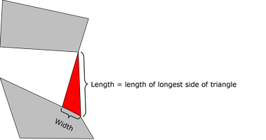
This parameter controls the lengths of triangles that form the connectors. The length of the triangle is defined by the length of its longest side (see figure below). This value should not be less than the Maximum Triangle Width. The larger its value, the farther apart two input polygons can be and still be connected together by triangles in the formation of amalgams.
In terms of triangle count, decreasing this value generally decreases (and will not increase) the number of triangles generated. Changes in this value are not expected to have a significant impact on performance. In terms of the appearance of the triangle connectors, having this value set too high could result in the input polygons being output as a single amalgam.

This parameter controls which holes should be eliminated from the amalgams. The larger its value, the larger the remaining holes will be. In terms of hole count, decreasing this value generally increases (and will not decrease) the number of holes remaining in the amalgams.
This parameter specifies the name of a list attribute for the amalgams. For each amalgam, this list will contain an entry for each input feature whose polygonal geometry shares a boundary with the amalgam. All attributes from the input feature are recorded in the list entry, except feature level attributes prefixed by fme_.
Note: List attributes are not accessible from the output schema in Workbench unless they are first processed using a transformer that operates on them, such as ListExploder or ListConcatenator. Alternatively, AttributeExposer can be used.
This parameter specifies the name of a unique identifier for the amalgams. If specified, each amalgam will receive an ID value that is unique across groups. All triangles and holes contained in an amalgam will receive the same ID as that amalgam.
Usage Notes
Dissolving the input is necessary to remove shared boundaries and overlapping regions, with which the AreaAmalgamator cannot be expected to function properly. However, dissolving the input has some side effects:
- If multiple input features dissolve into a single feature, then only one set of feature attributes are kept on the dissolved feature.
- If two input geometries share a boundary – for example, two peninsulas glued together – the user might expect triangle connectors to form between the two geometries when the Binary Amalgamation mode is selected. However, such geometries will first be dissolved, making it much more likely that Binary Amalgamation will not cause triangle connectors to form between the peninsulas. To overcome this issue, please select the Self, Binary Amalgamation mode.
If the Maximum Triangle Length specified is less than Maximum Triangle Width, the results may be unpredictable.
Editing Transformer Parameters
Using a set of menu options, transformer parameters can be assigned by referencing other elements in the workspace. More advanced functions, such as an advanced editor and an arithmetic editor, are also available in some transformers. To access a menu of these options, click  beside the applicable parameter. For more information, see Transformer Parameter Menu Options.
Transformer Categories
Search FME Community
Search for samples and information about this transformer on the FME Community.
Keywords: Amalgamator
