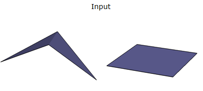
Features with replaced geometry are output through this port.
Replaces the geometry of a feature from donut, raster, or polygon to face. If the donut or polygon is not already three-dimensional, a 0.0 value for Z coordinates is assumed.
For a raster, the transformer will replace the geometry with a face with the same bounding box as the original raster with a textured appearance using the original raster, as applied from the top view.
The planar area has a concept of a surface normal, a vector that points outwards perpendicular from the area. The direction of the surface normal in a face is determined by using the right-hand rule: if the fingers of your right hand curl along the order of the vertices, the direction that the thumb points to is the direction of the surface normal.
Features with replaced geometry are output through this port.
Features which cannot be turned into a face and features with non-numeric attributes for Thickness or Surface Normal Deviation are output through this port.
Rejected features will have an fme_rejection_code attribute with one of the following values: INVALID_GEOMETRY_TYPE, INVALID_PARAMETER_SURFACE_NORMAL_DEVIATION, INVALID_PARAMETER_THICKNESS.
Select an option or choose an attribute. Automatic estimates a valid thickness for the geometry. Custom allows you to input your own thickness. Ignore ignores the thickness check entirely.
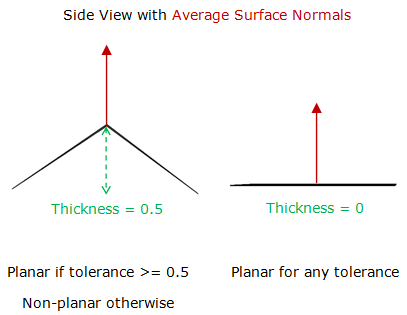
Enter a value or choose an attribute. The thickness tolerance is specified in ground units, and describes the maximum “thickness” a plane can have before it is considered non-planar. A planar polygon has a thickness of 0. A non-planar polygon will have its average surface normal computed using Newell’s method, and its thickness will be determined in the direction of the normalized surface normal.
For example, consider a single, non-planar polygon. Imagine a plane that passes through the world origin, with its normal set to the average normal of the polygon. Then, every point along the polygon boundary would be a distance D to the world plane. Relative to the world plane, we find the closest point and the farthest point along the polygon boundary. The difference between the farthest and nearest distances give us the desired thickness.


Select an option or choose an attribute. Automatic estimates a valid surface normal deviation for the geometry. Custom allows you to input your own surface normal deviation (in degrees). Ignore ignores the surface normal check entirely.
Enter a value or choose an attribute. The surface normal deviation tolerance is specified in degrees, and describes the maximum deviation from the average surface normal that a component can have before it is considered non-planar. A planar polygon has a surface normal deviation of 0. A non-planar polygon will have its average surface normal computed using Newell’s method, and the surface normal deviation of each part from the average surface normal will be computed with the cosine law.
For example, consider a single, non-planar polygon. Imagine a unit normal representing the average normal of the polygon. Now imagine a unit normal for each component of the polygon. The largest different between the average surface normal, and any other surface normal is the surface normal deviation.


Using a set of menu options, transformer parameters can be assigned by referencing other elements in the workspace. More advanced functions, such as an advanced editor and an arithmetic editor, are also available in some transformers. To access a menu of these options, click  beside the applicable parameter. For more information, see Transformer Parameter Menu Options.
Associated FME function or factory: @GeometryType
Search for samples and information about this transformer on the FME Knowledge Center.
Tags Keywords: 3DFaceCreator