A point cloud is a type of geometry that is useful for storing large amounts of data, typically gathered from LIDAR applications. The use of LIDAR allows for fast and accurate collection of data, such as for forestry canopy measurements, or landscape modeling.
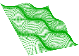
Point cloud geometry allows for quick and efficient processing of a large collection of vertices in 3D space that represent the external surfaces of objects. Together, these vertices form a model which can be transformed, and visualized. Some operations of the point cloud geometry involve thinning, splitting, and combining to produce a more useable set of vertices. This is an example point cloud image:
Associated with each vertex are a number of properties called components, which contain a value that describes the point.
These component values can be used to classify different sections of the collection of points contained in the point cloud geometry.
All components have a name and type. Possible component types are Real64, Real32, UInt64, UInt32, UInt16, UInt8, Int64, Int32, Int16, Int8, and String. Numeric components additionally may have a scale and offset factor; in such cases, the applied value of the component will be value x scale + offset. String components additionally may have an encoding.
While components may have any name, there are a few common components that exist in several formats. These components are described in the following table.
| Component Name | Description |
|---|---|
| x | The x component of the geometry. |
| y | The y component of the geometry. |
| z | The z component of the geometry. |
| intensity |
The magnitude of the intensity of the pulse return. |
| color_red | The red image channel value of the object at the point. |
| color_green | The green image channel value of the object at the point. |
| color_blue | The blue image channel value of the object at the point. |
| classification |
The class of the point. Categorizes a point into fields, such as ground, building, water, etc. Values correspond to the ASPRS LAS specification. |
| return | The pulse return number for a given output pulse. |
| number_of_returns |
The total number of detected returns from a single pulse. |
| gps_time | The number of seconds since the beginning of the week. |
| gps_week | The week number, counting from January 6th, 1980. |
| angle | The angle of the pulse that the point was scanned at. |
| flight_ line | The flight line number the point was detected in. |
| flight_line_edge | Specifies whether this point lies on the edge of the scan, along the flight line. |
| scan_ direction | The direction in which a scanning mirror was directed when the point was detected. |
| point_source_id | A value that indicates the source of the file, for example a file number. |
| posix_time | Used to express the time, as the number of seconds elapsed since UTC January 1st, 1970. |
| user_data | The user data value is for the user to use. |