Features read from Autodesk FBX files consist of geometry only. They have no user attributes.
An FBX file is a tree structure where each node may or may not have an associated geometry. An FME feature will be generated for each child of the root node of the FBX file.
Fbx_root: Note that some files have been observed with a root node that has a single child, where the child is named Fbx_Root. The child node usually has multiple children of its own, but these files will produce only a single feature. To split the single feature into multiple features, you can place a Deaggregator transformer in the workspace.
The only geometry type currently supported is mesh. All other geometry types will produce FME aggregate geometries. Each geometry linked to a child of the node will be added to the aggregate. Nested aggregates will result when the tree representing an FBX scene is multiple levels deep.
In the event that a node N, associated with a supported geometry (that is, a mesh), has child nodes CC also associated with geometries, an extra Aggregate A will be inserted in the FME representation. Aggregate A has two children: N's geometry and Aggregate B. Aggregate B will contain the geometries associated with CC. Aggregate A will be given the name fbx_parent_agg, and Aggregate B will be named fbx_children_agg.
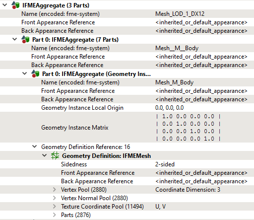
Each FBX node has a name, and each FME geometry output from the reader will have its name set to the name of the FBX node from which it originated. The image below shows an example of this structure in the Data Inspector's Feature Information pane:
All geometries are read from FBX as geometry instances; because an FBX geometry can be referenced from any number of FBX nodes, this ensures efficient representation.
FBX geometries and their parts may be associated with FBX materials, which correspond to FME appearances. An FBX material may have textures associated with more than one of its color properties, while an FME appearance is currently limited to a single texture. The reader looks for textures under the following property names in this order, and the first one with a valid texture will be used:
|
Order |
Property Name |
Notes |
|---|---|---|
| 1 | DiffuseColor | |
| 2 | EmissiveColor | |
| 3 | AmbientColor | |
| 4 | SpecularColor | |
| 5 | DiffuseTexture |
undocumented property name encountered in existing data |
| 6 | EmissiveTexture | undocumented property name encountered in existing data |
| 7 | SpecularTexture | undocumented property name encountered in existing data |
If additional textures are encountered, FME logs a warning.
Axis System
An FBX scene may have its axes configured in any direction. The reader will convert each scene before reading so that the up axis is Y, the axis pointing toward the viewer is Z, and the X axis is to the right (making the system right-handed).
FBX scenes created by FME will also always use this axis system.
Scene Units
When FME reads an FBX scene, it will output a log message stating what units the scene uses. Coordinate values will be read verbatim, unless the reader option Convert to Meters is selected.
FBX scenes created by FME will always use the default units (centimeters).